Key Fact
Due to the extreme dangers inherent with testing equipment at such high power, operator safety was of utmost importance

Testimonials
“A viable high throughput, safe and reliable test system for a very demanding and high-tech requirement.”
Understand
The Challenge
To provide a bespoke automated production test facility for Voltage Source Converters (VSC) and safely exercising the devices up to their operating limits of 2.5kV and 2000A. A Voltage Source Converter is a device which can be used to convert a direct current voltage into alternating current voltage.
The Solution
Developing a LabVIEW/TestStand PXI based system providing full automated production test of UUTs, whilst maintaining strict safety practices and procedures safeguarding both product and operators.
Introduction
As a National Instruments UK Gold Alliance member, specialising in using NI products to provide control, test and automation, TBG Solutions were invited by a high profile power generation and transmission company to provide a solution for their test requirement for their VSC sub-modules. The testing required the system to charge the products in pairs to in excess of 2kV, and then exercise their ability to generate AC when grouped, at over 2.5kV and 1800A peak whilst maintaining control and safety through monitoring of the product and the environmental conditions.

Engineer
Cell Design
Due to the extreme dangers inherent in the testing of these devices, the safety features of the test cell were foremost in the design. The safety features were based around operator exclusion from the cell during operation with hardware interlocks on doors which cut cell supply voltages, automatic VSC discharge paths on cell entry to protect against errant charge and stringent operating procedures for cell entry and loading. This can be seen in Figure 1.
The test cell can be broken down into six major parts;
1. Operators console- This housed the control PC and interface and primary interlock key control.
2. Test Cell- This is the walled exclusion zone that prevented contact with hazards through the use of 8 foot walls, flash proof filtered windows and an interlocked door.
3. 48U 19” power rack- This contained 2 MPE TS Series 4 3KV DC power supplies.
4. 48U 19” control rack- This housed the PXI chassis with associated signal conditioning and switching and communications interfaces for control and measurement.
This included;
a. PXI-1044 14 slot chassis.
b. PXI-PCI 8336 MXI-4 link.
c. PXI-8231 Gigabit Ethernet Interface.
d. PXI-8432/2 RS232 Interface.
e. PXI-4071 6.5 Digit DMM
f. PXI-5105 60MS/s 12 Bit 8 Channel Digitiser/Oscilloscope 128mb
g. PXI-6514 Industrial IO Card
h. PXI-2571 66 Channel, 1A SPDT Relay Module
i. PXI-6224 M-Series Multifunction DAQ Card.
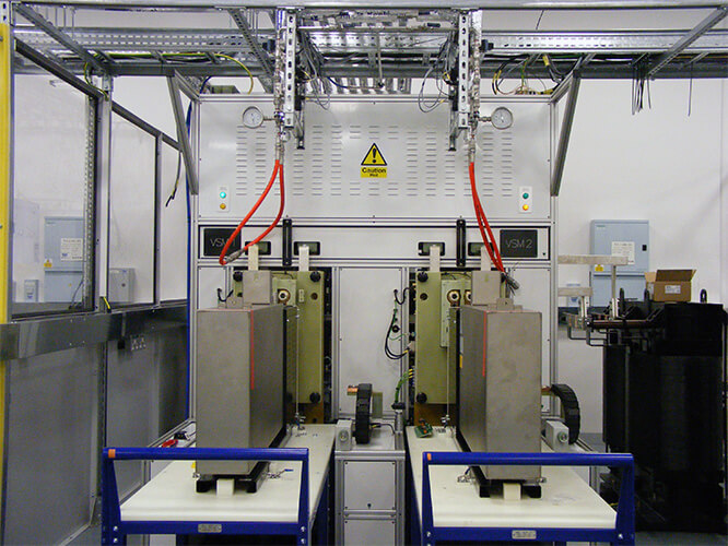
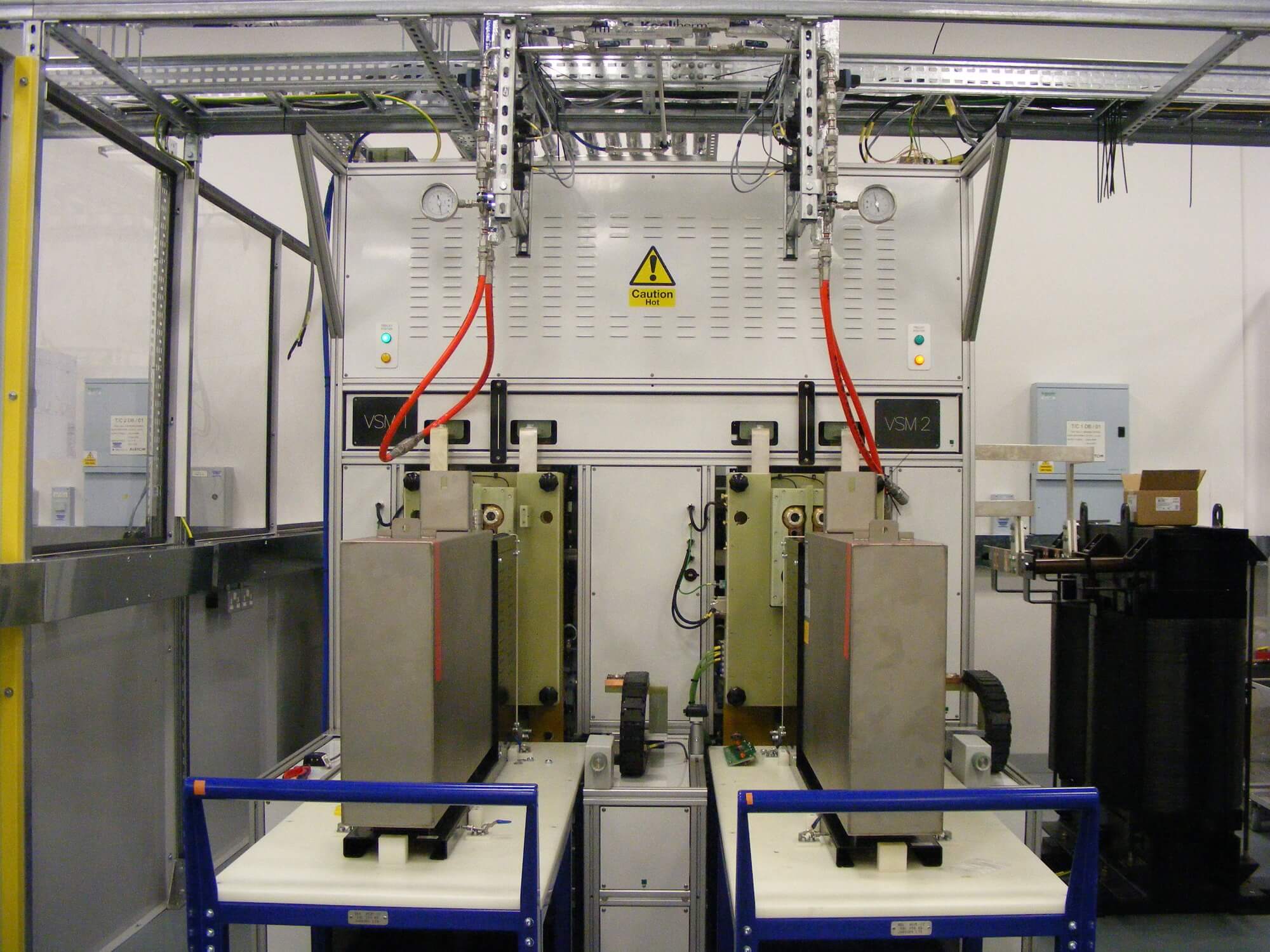
5. UUT interface- This was a freestanding structure which housed the pneumatics, cooling interface, bus bars and high voltage switching. The UUTs also plugged into this.
6. Cooling plant– This had a temperature controlled closed loop water cooling system that used deionised water.
The Test cell can be seen in figure 2


The system has two test bays; one for each UUT. The UUTs are brought into the system on trolleys as seen in Figure 3.
The UUTs are connected to the test cell via hydraulics once all operators vacate the test area and the doors are closed. Once the UUT Interface is connected, the tests can begin.
National Instruments Components-Hardware
One of the key safety concerns was a conductive path between the operator and the UUT. Thanks to NI this was easily overcome by using their fibre optic Ethernet link between the PXI chassis and the PC. This gave the added benefit that the PXI chassis did not require a controller, making the integrated cards appear as part of the PCI backplane. Another key feature of the NI hardware that accelerated development were the soft front panels, which shipped with the hardware and allowed direct control over instruments out of the box. This allowed commissioning of the very complex hardware independent of TestStand, giving us confidence in the test cell before we ran the automated test sequences.
National Instruments Components – Software
The software architecture was made up of several interfaces and engines which worked interactively to create a simple unified interface. This allowed an operator to automatically control a large and complex system. This particular system included complex control, data acquisition, cooling, critical safety monitoring and complex test and was also able to provide detailed debug and manual control capabilities. This can be seen in Figure 4.
The primary interface is a modified version of the shipped TestStand Operator Interface as seen in Figure 5 .
The interface is used by the Operators to run the test sequences and gives them live feedback on the status and progress of the UUTs. Another key modification to the interface was the ability to terminate a sequence in accordance with the safe practices required, when dealing with a high power system.
The second interface is the UUT Communications and Control interface.
The VSC constantly streams a status message over RS232. This is then processed by the interface into a usable format and made available to the TestStand sequences using a shared variable library. Commands are also sent to the VSM via this interface. During testing this runs in the background and requires no user interaction, but was very useful during commissioning and debug.
The third and final interface as seen by the operator is the Data Acquisition and Control Interface.
The Data Acquisition and Control Interface acts as an engine for the continuous data acquisition from the AI and DIO that required constant monitoring. It also included the software that controlled and monitored the cooling plant.


Deliver
Conclusion
TBG Solutions provided a high throughput, safe and reliable test system for a very demanding and high-tech requirement. The soft front panel tools, hardware abstraction layer and easy integration of a variety of instruments allowed rapid development and verification.
