Doosan Case Study

Doosan Group is a South Korean conglomerate company. The business operates across many sectors, which includes power plants, engines, construction equipment and machine tools. Employing 43,000 people, Doosan Group is a Fortune 500 company.

Key Fact

Added advantage of fast and easy implementation of new software features

Testimonials

“This new system caters for the easy addition or removal of functionality from the system”

Understand

The Multi Fuel Burner Test Facility (MBTF) in Glasgow, Scotland, is used to test different coal furnace technologies in addition to being capable of testing numerous different types of coal fuel. The plant control system was originally implemented using National Instruments (NI) FieldPoint hardware, and NI Lookout software. Due to global environmental pressures, there is now a requirement to test numerous different ‘clean burn’ technologies and fuels. TBG has implemented a major upgrade to the MBTF software, replacing the existing Lookout code with a more powerful LabVIEW™ system. This new system caters for the easy addition or removal of functionality from the system as may be required by the various burn technologies under test.

Engineer

The plant comprises more than 450 data channels used for data acquisition and control. Plant control, data analysis and trending are performed by three different PCs: a master PC controls the plant’s hardware, and two remote PCs are used to view the data from all sensors within the plant, producing historical trends and data logs, which are required by the owner of the technology under test and also the Scottish Environmental Protection Agency (SEPA).

Using the original system as software specification, all of the necessary objects, logic and functionality in Lookout were redesigned using LabVIEW, ensuring the new software mimics the look and feel of the original Lookout system. The system is divided into nine sections such as water cooling, furnace ignition or coal transport, allowing the operator to easily switch between each of the different screens.

The main design challenge was to determine the functionality of the original system through analysis of the existing Lookout code. It emerged that understanding the code alone was not sufficient to ensure that the LabVIEW system would operate correctly. As a result it was necessary to obtain a thorough understanding of the mechanics of the system through the study of existing flowcharts, wiring diagrams and hardware schematics. This had the added benefit of allowing us to be more capable at finding faults during the commissioning of the system.

Deliver

Doosan Babcock now use a system that has the same functionality, look and feel as its original Lookout system. It does, however, have the added advantage of fast and easy implementation of new software features that reflect any necessary hardware changes required to the furnace architecture to test future coal burning technologies.
University Of Manchester Case Study

The University Of Manchester is a leading research university focused on achieving real world impact beyond academia. It is at the forefront of tackling disease, poverty and sustainable energy solutions.

Key Fact

In Nigeria, oil theft from pipelines accounts for the loss of 20% of Nigerian oil, amounting to $150 million per day and causing significant environmental damage.

Testimonials

“The prevention of oil theft will in turn prevent environmental damage from spilt oil.”

Understand

In Nigeria, oil theft from pipelines accounts for the loss of 20% of Nigerian oil, amounting to $150 million per day and causing significant environmental damage.

The challenge was to develop a system that could provide instant theft warnings. A system such as this would be of enormous value to the oil industry. The solution would also become a strong deterrent to future theft with the threat of a quick detection and response.

The project was a collaboration between TBG Solutions and The University of Manchester funded by the Technology Strategy Board.

Engineer

The system needed to be:

Reliable: able to distinguish between vibration events that are not attacks.
Covert: hard to detect with no visible signs of the installation that would attract attention and reveal the location of the system; preventing tampering or removal.
Wireless: providing independence so that the system is not reliant on a single link, which can be costly and unsecure.
Robust: requiring no servicing for many years while the system is operational.
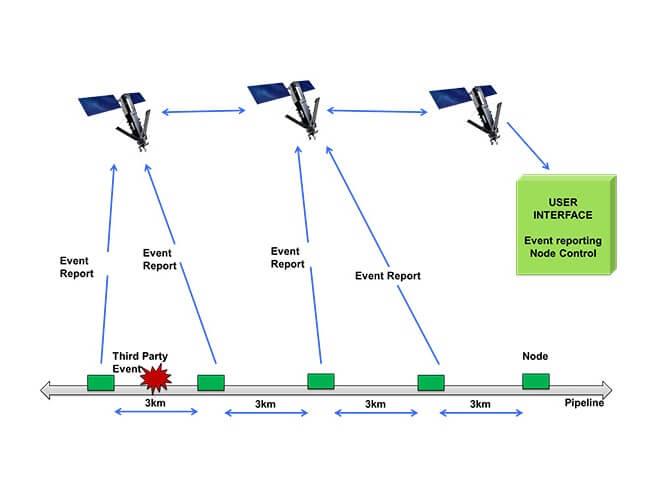
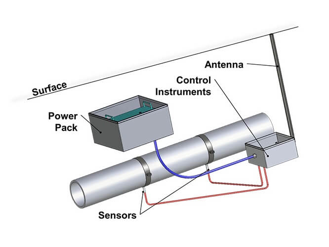
The wireless (via satellite link) sensor nodes were positioned at 3km intervals along the pipeline. Expandability in design allow the system to be deployed across many hundreds of kilometres. Algorithms were developed that used vibration data to accurately pinpoint theft locations.

Deliver

The finished design was successfully demonstrated across a 1km test loop in Scotland.

The successful implementation of this project would provide Nigeria with a strong method of preventing valuable oil theft and greatly reduce the environmental impact from spilt oil.

Building a Scalable Antenna Test System Case Study

A case study on an Antenna Test System we built for one of our customers to test the antenna response on a user-defined range of frequencies.
Key Fact

The system can test the antenna response on a user-defined range of frequencies (expanding on the limited S and X Bands), both stationary, and along the length of the antenna.

Testimonials

“The Antenna Test system exceeded the original Test Software surpassing the test specification and has now replaced the old system completely in a production environment as confidence in the software is so high.”

Understand

Introduction

Modern technology heavily relies on a wide range of transmissions, from simple AM Radio to Satellite Tracking Systems. All EM Communications require an antenna for both Transmission and Reception, making the production and supply of antennas a huge industry. Some suppliers push the boundaries on antenna size providing devices we rely on every day to be smaller and slimmer, such as Mobile Phones or the Bluetooth Antenna in your Smart Watch. Others, as in the case of our customer, push the boundaries on complexity, providing smarter RADAR and Detection systems that keep Ships and Aircraft safe.

TBG Solutions was contracted by the customer to update an existing Antenna Test System, written in a now unsupported software language. Unfortunately, the Source Code was no longer available and Test System had to be redesigned from scratch. TBG Solutions was involved from the beginning of the update project, to design and implement a modern test system. The test system needed to be expandable, hardware independent and compatible with multiple Network Analysers.

Antennas

Antennas are using in a wide range of industries and vary dramatically by both size and complexity. The range of frequencies each antenna is designed and tuned for can also vary significantly. The Antenna Test System was designed to test large RADAR antennas, designed and supplied to the Marine Industry. The frequency range of the Antenna Test System covers both the S and X Bands. S-Band covers 2-4GHz and is used by Surface Ship RADAR, as well as some communications satellites. The X-Band however, covers the higher range of 8-12GHz and is used in military Satellite Communications, along with more advanced RADAR.
Engineer

Our Solution was a system that could test the antenna response on a user-defined range of frequencies (expanding on the limited S and X Bands), both stationary, and along the length of the antenna. These measurements included both Phase and Magnitude on both Transmission and Reception, and measurements could also be expanded to include frequency sweeps at differing power levels. This gave the user full control over the measurement type.

Test System Design

The Modernised Test System was designed using NI LabVIEW Object Orientated Programming, along with an NI GPIB Card to Communicate to a Network Analyser which is used to conduct the tests. Due to the expandable nature of LabVIEW, especially when developed using Object Orientated Design Principles, we were able to design a system that could be quickly and easily updated to work on any programmable Network Analyser.

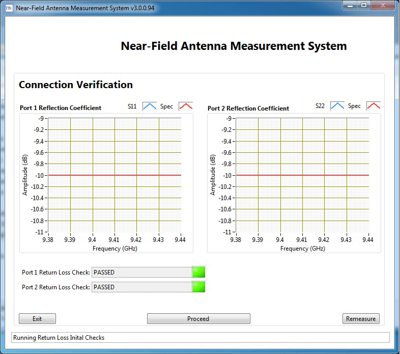
The Analyser was used to capture the responses to both transmission and reception for a specific Antenna. The test system captured “S” measurements (S11, S21, S22) and calculated both Phase and Magnitude for the captured responses.

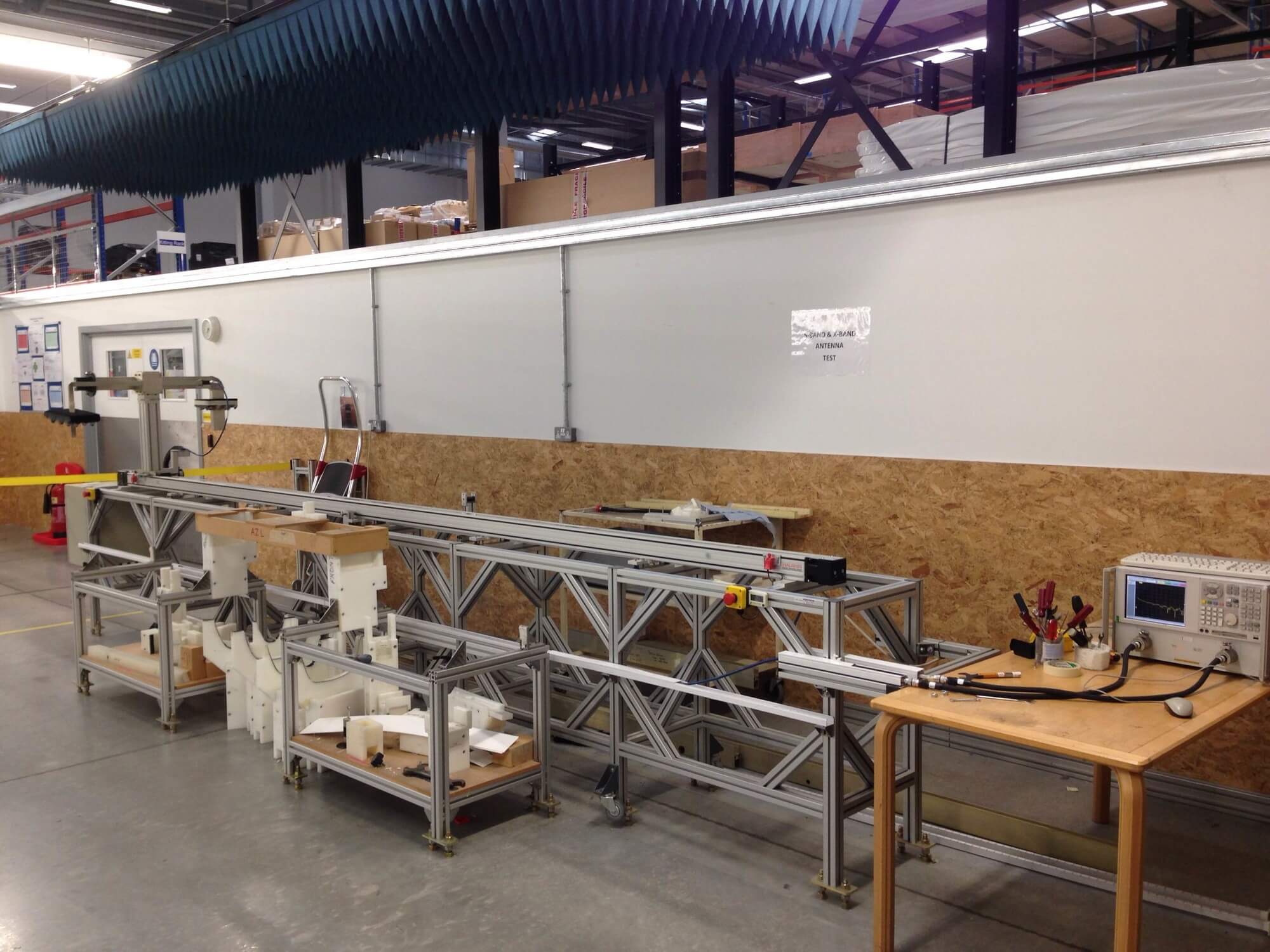
The Antenna Measurement System Hardware

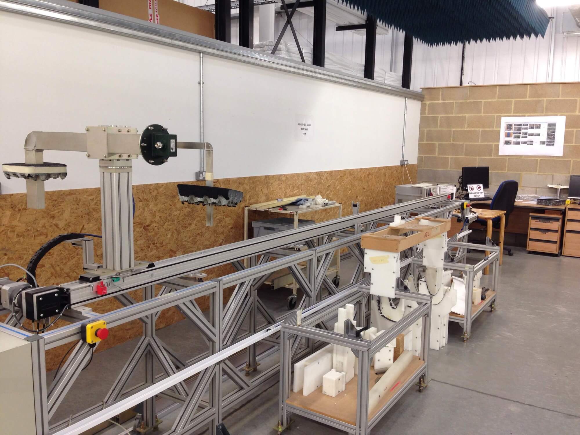
The test system also comprised of a Step Motor that allowed the Test Software to move the test probe along the length of the antenna while simultaneously taking measurements. This allowed our customer to build a complete antenna profile which could be used in both design and verification activities. This data was then post analysed to generate Near Field and Far Field data allowing our customer to verify that their antenna or component was functioning correctly and responded as expected in real-world tests.

The Antenna Measurement Probe

Test System Software

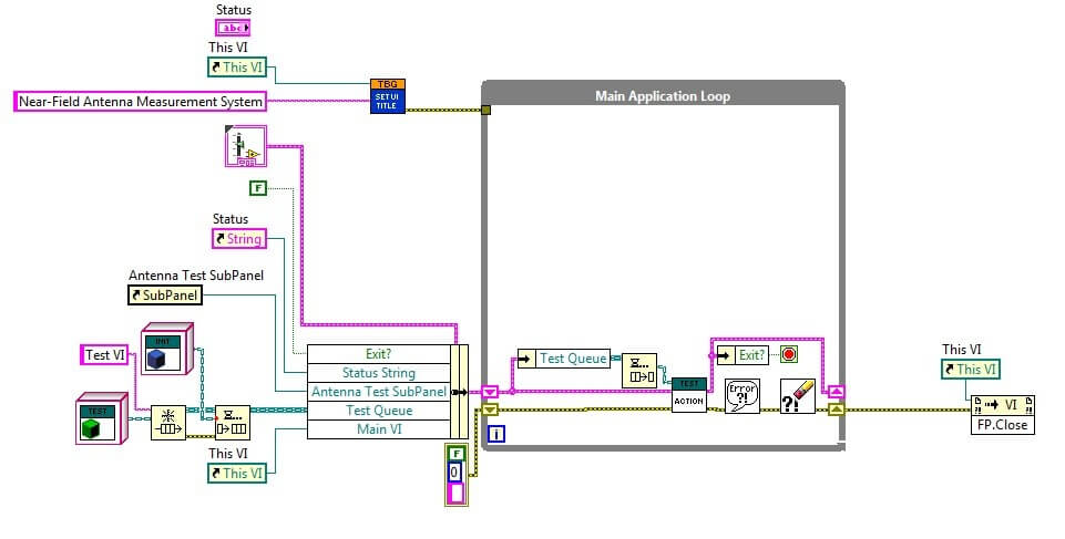
The control software for the Antenna Test System was written entirely in National Instruments LabVIEW. Using LabVIEW allowed us to construct an expandable and complex test system in a much shorter time than other text-based languages. The graphical nature of LabVIEW also allowed us to easily demonstrate the functionality and instruct our customer on making minor modifications to the functions of the Test System.

The Test System software was completed using Object Orientated Design principles which allowed us to develop Simulation Modules of all of the hardware in the system. This made debug very simple and independent of hardware. Once this was complete we were able to more easily develop modules for physical hardware (two different Network Analysers were required to be compatible, with more in the future).

Object Orientated Programming is a framework that allows code to be written using a generic module or “Class” for each of the functions of a piece of hardware (or function). An example would be taking a reading from a Network Analyser. This generic module is then used to create a specific module for a specific piece of hardware creating a “Child Class”. There can be multiple Child Classes with one for each specific piece of hardware. These Child Classes are automatically substituted when the software is run depending on the hardware element is selected. This makes adding new hardware simple as no changes to the software’s code are needed to facilitate additions. (except creating a new Child Class).

While coding modules, LabVIEW automatically checks that all the requirements for a Class are met, and reports any issues clearly. This allows an Object Orientated System to be coded by a developer with limited knowledge of the principles behind its operation.

The Antenna Measurement System Software
LabVIEW Object Orientated Programming Streamlines Code

Deliver

Results

The Antenna Test system exceeded the original Test Software surpassing the test specification. This Test System has now replaced the old system completely in a production environment as confidence in the software is so high. The system not only improves reliability, it also expands in the following areas:

·        Data is provided at a much lower level, as well as a top-level result, allowing our customer to investigate design issues at a much lower level.

·        The New System is already compatible with two differing hardware sets (which surpasses the old system), With more to be added as required.

·        Our Customer is no longer tied to a specific (and expensive) Network Analyser, they are now free to explore cheaper options.

Automated Test System for Critical Testing of Aerospace Grade Units Case Study

We converted an existing manually controlled friction brake test system into a software-controlled automated test system, critical for testing aerospace-grade units.

Key Fact

The software needed to allow the operator to control all aspects of a Parker Compax3 drive and MH series 10000rpm motor.

Testimonials

“The system ensures a level of quality control that is required by a modern Aerospace company.”

Understand

The customer is one of the world’s leading Aerospace companies, specialising in actuator and motor systems for a range of aircraft.

They approached TBG with the requirement to convert an existing manually controlled friction brake test system into a software controlled automated test system, critical for testing aerospace grade units. The software needed to allow the operator to control all aspects of a Parker Compax3 drive and MH series 10000rpm motor.

Initially, the customer was told by other integrators that this would not be possible. However, the experience of TBG Solutions and our capabilities gave us the confidence that this could be done and not only could we produce the software in house, but also make use of our in house mechanical and electrical expertise to make changes to the inner workings of the test rig to allow for full control in software.

Engineer

The Solution

The solution is a bespoke LabVIEW application that allows for full control of the motor drive as well as a profiling application to allow for automation and sequencing of ramp rates and dwell times, to fulfil the critical test specification of the UUT.

We were able to make use of the LabVIEW IDE and its prebuilt functions for serial RS232 communications to build a OOP based HAL for the Parker Compax3 Motor Drive. This provides flexibility and scalability for communication between multiple systems and different motors.

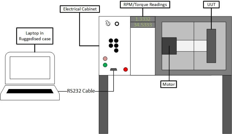
Feedback from this Parker Compax3 motor is also displayed on COTS indicators showing the speed and torque on the shaft and UUT. The system itself connects via RS232 to a laptop within a rugged Pelican case designed and manufactured in house by TBG solutions to the highest standards. A basic system overview can be seen in Figure 1.

The Application

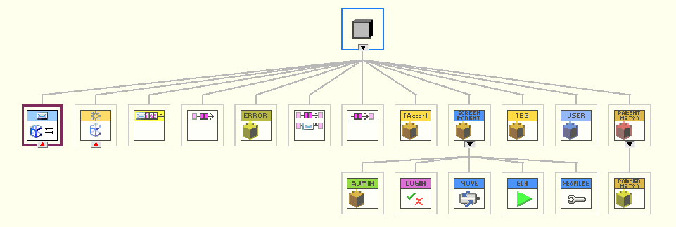
The application makes use of the OOP programming architecture. This coupled with TBGs own OOP based QMH design pattern allows for a scalable application architecture where events and error handling are organised and reliable.

Figure 1 - General System Overview
Figure 1 – Class Hierarchy

Communications

The key challenge in this project was working to ensure that we could achieve stable and reliable communications with the 3rd party device. Due to there being no driver being provided by the manufacturer, TBG had to revert to using our experience in driver production as well as the comprehensive serial communication user manual for the motor drive. The driver created is the first of its kind for the Compax3 series of motor drives. LabVIEW’s acceptance of a HAL environment means that the software is scalable to multiple test sets and can be transferred over to other motors and drives in the Parker portfolio. The HAL based driver set for the motor drive handles all initialisation, read/write, error handling and shutdown controls for the motor drive. An example of the read-write code can be seen in figure 2.

Figure 2 – Motor Read/Write Driver

User Interface

The User Interface of the application can be split into 4 discrete parts which are:

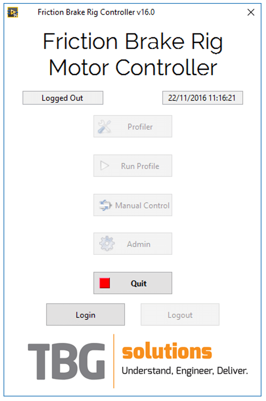
·        Main Interface – This the main launcher where a user can select different screens dependent on their requirements such as the profile editor, manual control or even user management. All buttons are enabled/disabled based upon the user’s credentials (i.e. admin, engineer or operator).

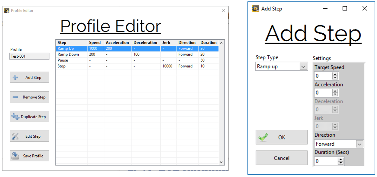
·        Profiler – This is where the user can create or edit a test profile for UUT testing. They have full control over adding and removing steps. When adding steps, they can ramp up, ramp down, dwell or stop. The add step popup will dynamically change the available step options based upon the step chosen. The options include direction, acceleration and speed.

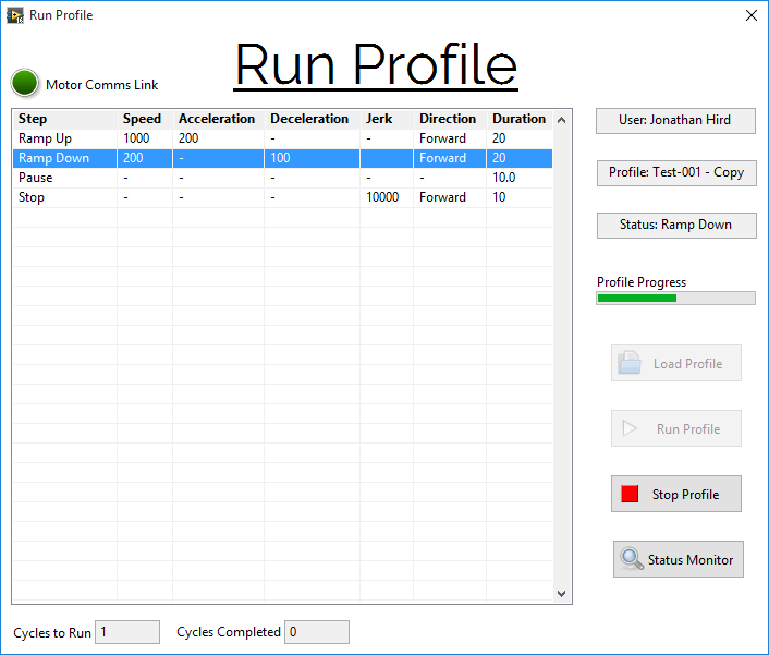
·        Run Profile/Test – This is where a profile can be loaded and run, and in turn, commands sent to the motor drive to test a UUT (as seen in figure 5).

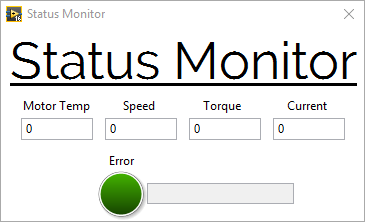
The user can see the loaded steps of the profile and can set the system to run multiple cycles of the same test whilst viewing critical data such as motor temperature and voltage via an asynchronously loaded status monitor, as seen in figure 6.

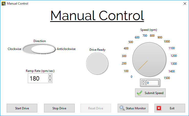
·        Manual Control – As well as automating the test procedure, the user may require manual control of the motor to debug a potential issue with the UUT or run the UUT to a high speed with maximum control. This is done via a dedicated manual control screen (as seen in figure 7) which utilises the same HAL based commands to the motor drive. The screen is constantly monitoring interlock and e-stop conditions to ensure that operation can’t take place whilst a guard door is open or when the system is in an E-Stop situation. The user is granted full control of direction, ramp rate and speed with this screen whilst again making use of viewing critical data in the status monitor.

Figure 3 – Main Interface
Figure 4 – Profile Editor and Step Editor
Figure 5 – Profile Editor and Step Editor
Figure 6 – Status Monitor
Figure 7 – Manual Control Screen

Deliver

Since delivery, the system has tested hundreds of units and runs daily with the customer reporting good feedback on the usability and reliability of the system, keeping them on track in terms of units tested and keeping them at the forefront of the aerospace industry. The use of the LabVIEW OOP capabilities allowed us to create an application that not only exceeds customer expectations but also allows for a fully scalable design architecture which serves as a base foundation for further systems and other projects.

Automated Test System for Functional and In-Circuit Testing Case Study

The automated test system we developed for functional test and in-circuit testing allows testing for multiple product ranges and is easily scalable for future expansion requirements.

Key Fact

New products can be supported by designing additional interchangeable test adaptors (ITA) which can be easily fitted to the system

PCB Test

Testimonials

“TBG Solutions delivered a functional test system that is effective and easily expandable.”

Understand

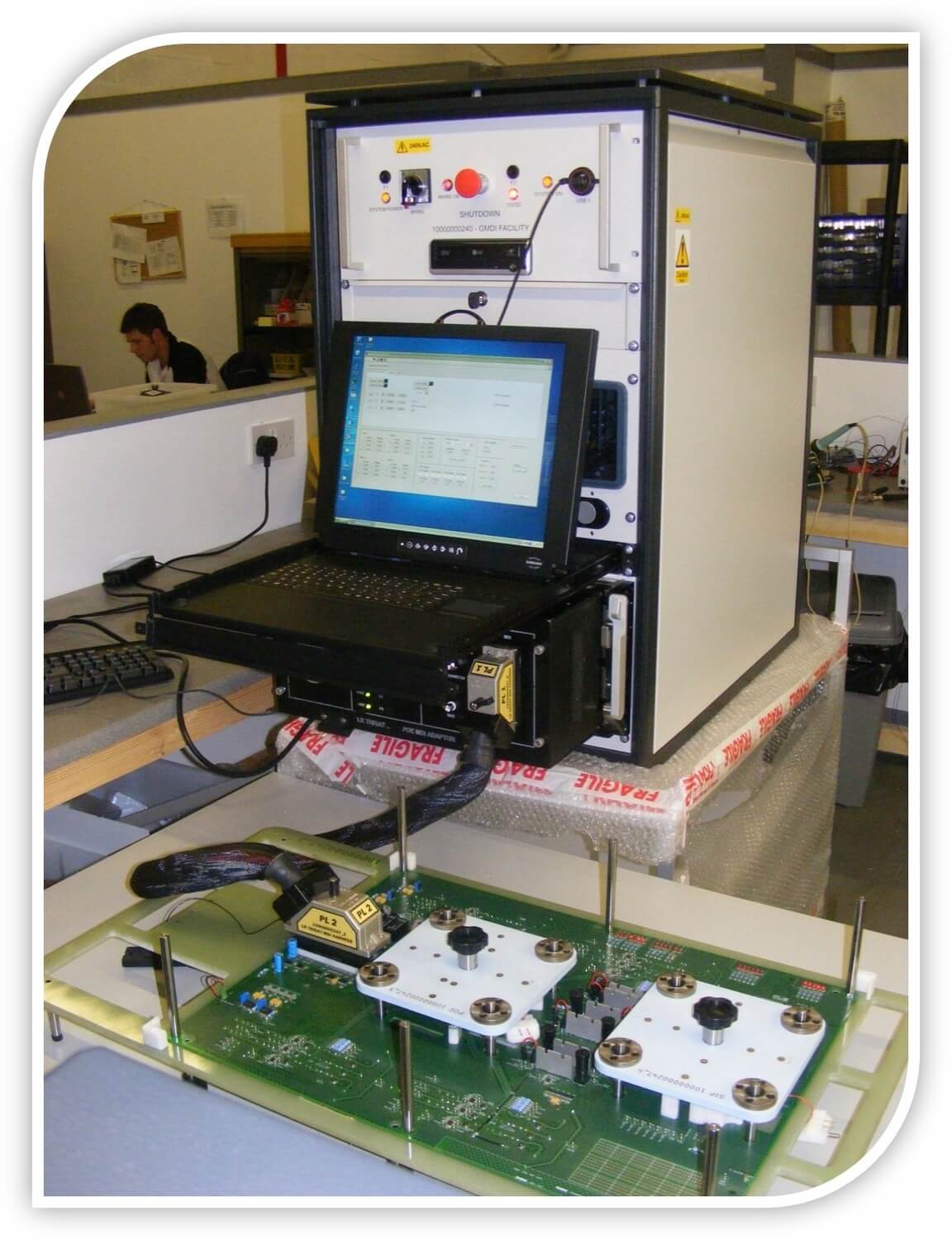
TBG Solutions have produced a PXI based generic automated test system performing both functional test and in-circuit testing on multiple products ranges.

The system leverages the MacPanel scout interface to provide a reconfigurable base platform from which the system can easily and quickly adapted in order to test a wide range of products. The system comprises enough hardware to support most test functions and can be expanded to support additional hardware where required.

The software architecture is modular and comprises elements common to all product test applications such as user management, calibration and diagnostics. The software is expanded to facilitate product specific testing by implementing custom TestStand sequences. New products can be supported by designing additional interchangeable test adaptors (ITA) which can be easily fitted to the system. New software sequences can be written specifically for each ITA expanding the functionality of the system.

Engineer

Design Challenges

The challenge was to design a versatile PXI based system incorporating a mixed suite of measurement hardware that can be re-configured and re-used for testing multiple product types using a commaon base platform. A product specific Interchangeable test adaptor is attached to the base system to provide the signal routing and configuration applicable to the tests required for that specific product.

Due to the nature of the project there would be a lot of electrical noise, limiting the distance that data could be transmitted. This posed a problem since operations needed to be logged at high accuracy and in real time.

System Design

National Instruments PXI measurement hardware provides the basis for the Generic Manufacturing Defect Inspection Automated Test Equipment (GMDI-ATE) which is further augmented using Excelsys Xgen™ range power supplies. The system is mounted in a standard 19” rack enclosure and incorporates a MacPanel Scout interface for configuring the system for different applications.

NI-PXI hardware modules provide a large number of analogue and digital channels working in tandem with high density switch and relay matrixes. In addition, we include a high precision DMM, arbitrary function generator, fully reconfigurable FPGA, RS232/485 serial communications, CAN and JTAG boundary scan.

Deliver

The systems delivered to date have successfully managed to reduce the cost of ownership and lead times on providing new test capabilities whilst improving test performance, accuracy, traceability and throughput. TBG can augment your test capabilities by designing and producing an ITA in under eight weeks.

In-Circuit Test System

Testing Electronic Power Assisted Steering Systems (EPAS) Case Study

The Multi-Axis Motion Test Facility that we developed allows the customer to rapidly prototype, test and perform custom measurements on any of their EPAS product range.

Key Fact

The system was developed using an object-orientated approach in order to maximise the scalability of the test rig

Testimonials

“The new system gives us a huge degree of freedom and significantly reduces the time it takes us to build new test procedures.”


Understand

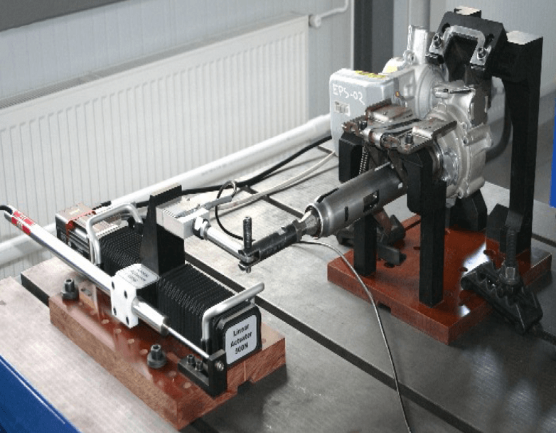
Our customer is a global supplier of automotive systems, modules, and components to automotive original equipment manufacturers and related aftermarkets. We have provided them with a flexible multi-axis motion test facility capable of controlling up to four individual drives to be utilised in tests performed on Electronic Power Assisted Steering (EPAS) racks, used in a large variety of automobiles. The system provides the capability to determine the quality of their products through measurements such as friction and hysteresis.

Engineer

Design Challenges

The main design challenge in this system was to provide a flexible interface and control architecture that allows our customer to research and design a large variety of tests that can be undertaken using any number of motion axis. Being capable of writing detailed and complex testing scripts through an intuitive user interface allows the customer to rapidly prototype, test and perform custom measurements on any of their EPAS product range.

The next main challenge was to ensure that the software contained safeguards to protect the product samples under test from over application of load or torque. As a result, alarm limits for selected sensors are saved within the motion profiles, so that custom load and position limits can be applied depending on which test is being performed. This eliminates any risk of damage to hardware when developing new tests.

System Design

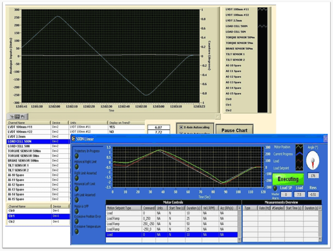
The system was developed using an object-orientated approach in order to maximise the scalability of the test rig. The system is capable of independently running up to four motion profiles on two rotary and two linear actuators. Typically the software is used to control the application of load or apply a deflection to a test sample for the purpose of calculating stress and performance measurements. In addition to the four motion axis, there is a brake controlled from a calibrated voltage output. This allows the test designers to apply a load/torque onto one end of a steering rack and apply an independent braking torque at the opposite end of the test piece, effectively controlling the torsion. In addition to the control aspects, there is a sophisticated data acquisition routine that acquires data to a log file at high speed for offline analysis in addition to displaying the test results on a live trend screen.

Deliver

Our customer now has the capability to design and run a variety of tests in which there is an unprecedented degree of freedom. As a result of the reduced time taken to develop and build new test procedures, the rig is now under large demand to perform production tests in addition to purely being used as a platform for researching and developing new tests.

The Multi-Axis Motion Test Facility
Monitoring window

Drillpipe Inspection System Case Study

GE Energy provides a broad array of power generation, energy delivery, and water process technologies to solve global challenges. The Power & Water division works in several areas of the energy industry, including wind and solar, biogas, and alternative fuels.

Key Fact

The system of sensors needed to be highly adaptable and configurable in order that multiple systems could be tested

Testimonials

TBG Solutions delivered a reconfigurable, expandable and synchronised data logging network for full scale tidal turbine power train testing.

Understand

The Challenge

Creating a hardware and software test solution to allow full control of specialised Drillpipe inspection units.

The Solution

Using NI LabVIEW, a cDAQ-9174 Chassis with 1 x NI 9239 and 2 x NI 9403 modules, a customised TBG PCB and wiring harness allowed for full control of the hardware interface (Figure 3). This enabled the client to perform, monitor and record a number of tests including transverse flaw detection and wall loss detection.

Introduction

Drill pipe inspection is an important process that helps to maintain the safety and reliability of piping operations. Our customer are continuously looking for ways in which they can improve their products. Upon identifying the need for a new system, they developed a hardware interface which encapsulated two inspection capabilities. However, they needed an underlying software & hardware solution to truly improve the inspection process. They chose TBG Solutions to challenge the issue.

Engineer

System Overview

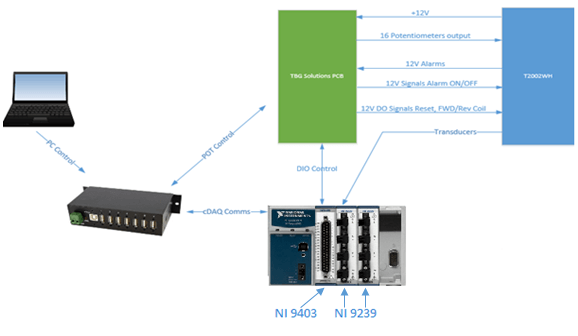
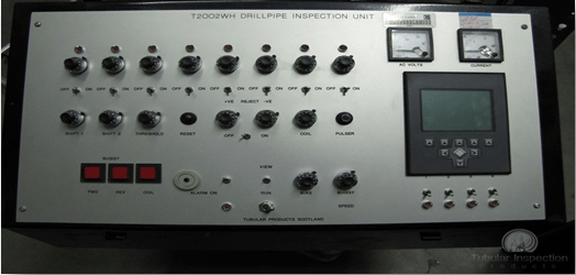
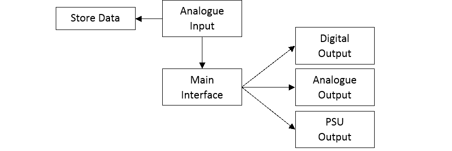
The system consists of a hardware interface with various physical switches and knobs which connects to the TBG PCB housing via various inputs and outputs. This included potentiometer outputs and alarm signals. The PCB I/O is controlled via the NI 9403 module in the cDAQ-9174 chassis which then connects to the PCB. The hardware interface also connects to the NI 9239 module which provides an input for the transducers. The cDAQ-9174 is connected to the control PC which enables the system to continuously send and receive data. Figure 1 is a graph outlining the physical connections between the described components.

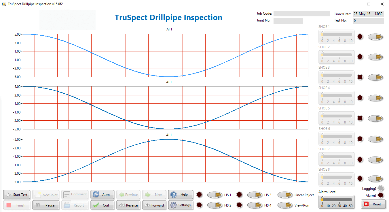
The software was developed in LabVIEW and uses various tools which are explained later in the case study. The software receives data from the coil transducers and the Hall Effect sensor and plots it onto graphs located on the main interface. Furthermore, the front panel controls provide an interface for controlling the physical components seen in Figure 2.

Figure 1 - System Overview
Figure 2 - Hardware interface for the T2002 inspection unit

Implementation

We designed the software to continuously receive data from the analogue inputs whilst offering the ability to manage the inspection unit through various digital and analogue outputs – all from a centralised location.

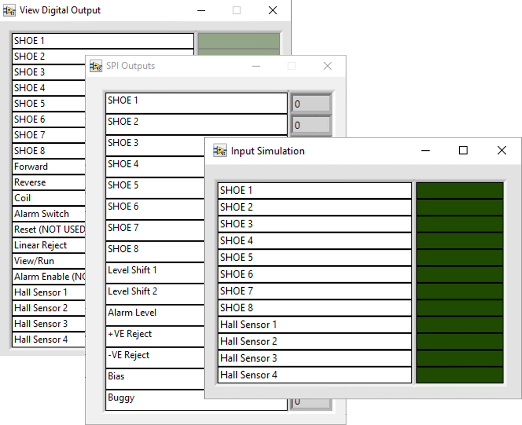
We used LabVIEW’s Object-Oriented Programming (OOP) architecture as this was an ideal tool to encapsulate each I/O type and create additional instances that could be dynamically dispatched inside the code. Using the OOP architecture increased the ease of development allowing us to produce simulation classes. This provided an I/O testing platform (Figure 4) for validating functionality throughout the development process and also allowed us to highlight any bugs that had been introduced. Due to the nature of the project, it was not viable for TBG to have access to the inspection hardware. By implementing the simulation classes, we were able to produce and test the software off-site, lowering the development costs and resolving any issues without having to involve the client.

Another invaluable tool that LabVIEW OOP offers is a graphical class hierarchy view (Figure 5) which enabled us to easily develop a Hardware Abstraction Layer (HAL). This greatly benefited the solution and allowed us to program the software in a way that would match the modularity of the NI hardware setup. This allowed us to accommodate potential software and hardware changes as new child classes, modifying the functionality without having to explicitly change the overall software.

Figure 5 - LabVIEW Class Hierarchy
Figure 3 - Simplified software structure
Figure 4 - I/O Testing Platform

Operator PC Interface

We used a number of LabVIEW front panel elements to achieve the full functionality required by the client. LabVIEW’s front panel tools allowed for the complex interface to be organised quickly and professionally while not compromising the ease of use. The front panel was divided using a tab control, allowing the user to quickly switch between screens of neatly organised controls and indicators. Furthermore, the ability to customise controls made the program more intuitive and straight-forward in use as each button was personalised with a unique icon.

Figure 7 - Settings interface
Figure 6 - Main interface

Deliver

Producing this solution required both hardware and software capable of interfacing with a number of inspection units. Using NI LabVIEW, a cDAQ-9174 Chassis with 1 x NI 9239 and 2 x NI 9403 modules and a customised TBG PCB and wiring harness, TBG were able to create a flexible and expandable solution capable of accommodating future changes in our customers requirements. Our solution enabled the monitoring of drill pipes, identifying defects before failure and possible damage.

How We Automated High Voltage Production Test

GE Energy provides a broad array of power generation, energy delivery, and water process technologies to solve global challenges. The Power & Water division works in several areas of the energy industry, including wind and solar, biogas, and alternative fuels.

Key Fact

The system of sensors needed to be highly adaptable and configurable in order that multiple systems could be tested

Testimonials

“TBG Solutions delivered a reconfigurable, expandable and synchronised data logging network for full scale tidal turbine power train testing.”

Understand

The Challenge

To provide a bespoke automated production test facility for Voltage Source Converters (VSC) and safely exercising the devices up to their operating limits of 2.5kV and 2000A. A Voltage Source Converter is a device which can be used to convert a direct current voltage into alternating current voltage.

The Solution

Developing a LabVIEW/TestStand PXI based system providing full automated production test of UUTs, whilst maintaining strict safety practices and procedures safeguarding both product and operators.

Introduction

As a National Instruments UK Gold Alliance member, specialising in using NI products to provide control, test and automation, TBG Solutions were invited by a high profile power generation and transmission company to provide a solution for their test requirement for their VSC sub-modules. The testing required the system to charge the products in pairs to in excess of 2kV, and then exercise their ability to generate AC when grouped, at over 2.5kV and 1800A peak whilst maintaining control and safety through monitoring of the product and the environmental conditions.

Engineer

Cell Design

Due to the extreme dangers inherent in the testing of these devices, the safety features of the test cell were foremost in the design. The safety features were based around operator exclusion from the cell during operation with hardware interlocks on doors which cut cell supply voltages, automatic VSC discharge paths on cell entry to protect against errant charge and stringent operating procedures for cell entry and loading. This can be seen in Figure 1.

The test cell can be broken down into six major parts;

1.      Operators console- This housed the control PC and interface and primary interlock key control.

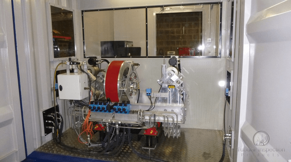
2.      Test Cell- This is the walled exclusion zone that prevented contact with hazards through the use of 8 foot walls, flash proof filtered windows and an interlocked door.

3.      48U 19” power rack- This contained 2 MPE TS Series 4 3KV DC power supplies.

4.      48U 19” control rack- This housed the PXI chassis with associated signal conditioning and switching and communications interfaces for control and measurement.

This included;

a.      PXI-1044 14 slot chassis.

b.      PXI-PCI 8336 MXI-4 link.

c.      PXI-8231 Gigabit Ethernet Interface.

d.      PXI-8432/2 RS232 Interface.

e.      PXI-4071 6.5 Digit DMM

f.       PXI-5105 60MS/s 12 Bit 8 Channel Digitiser/Oscilloscope 128mb

g.      PXI-6514 Industrial IO Card

h.      PXI-2571 66 Channel, 1A SPDT Relay Module

i.        PXI-6224 M-Series Multifunction DAQ Card.

5.      UUT interface- This was a freestanding structure which housed the pneumatics, cooling interface, bus bars and high voltage switching. The UUTs also plugged into this.

6.      Cooling plant– This had a temperature controlled closed loop water cooling system that used deionised water.

The Test cell can be seen in figure 2

Production Test System
Figure 1-Test Cell Enclosure
Test Cell
Figure 2-Test Cell
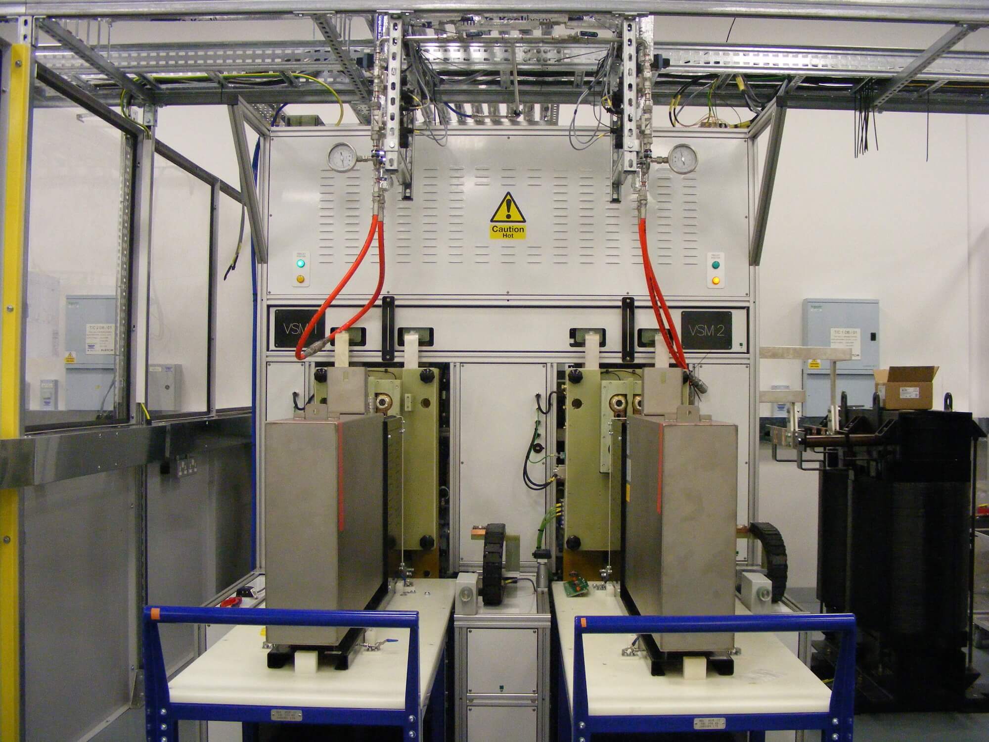
Test Cell with UUTS
Figure 3-Test Cell with UUTS

The system has two test bays; one for each UUT. The UUTs are brought into the system on trolleys as seen in Figure 3.

The UUTs are connected to the test cell via hydraulics once all operators vacate the test area and the doors are closed. Once the UUT Interface is connected, the tests can begin.

National Instruments Components-Hardware

One of the key safety concerns was a conductive path between the operator and the UUT. Thanks to NI this was easily overcome by using their fibre optic Ethernet link between the PXI chassis and the PC. This gave the added benefit that the PXI chassis did not require a controller, making the integrated cards appear as part of the PCI backplane. Another key feature of the NI hardware that accelerated development were the soft front panels, which shipped with the hardware and allowed direct control over instruments out of the box. This allowed commissioning of the very complex hardware independent of TestStand, giving us confidence in the test cell before we ran the automated test sequences.

National Instruments Components – Software

The software architecture was made up of several interfaces and engines which worked interactively to create a simple unified interface. This allowed an operator to automatically control a large and complex system. This particular system included complex control, data acquisition, cooling, critical safety monitoring and complex test and was also able to provide detailed debug and manual control capabilities. This can be seen in Figure 4.

The primary interface is a modified version of the shipped TestStand Operator Interface as seen in Figure 5 .

The interface is used by the Operators to run the test sequences and gives them live feedback on the status and progress of the UUTs. Another key modification to the interface was the ability to terminate a sequence in accordance with the safe practices required, when dealing with a high power system.

The second interface is the UUT Communications and Control interface as seen in Figure 6.

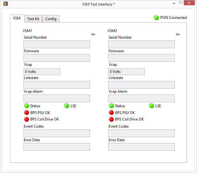
The VSC constantly streams a status message over RS232. This is then processed by the interface into a usable format and made available to the TestStand sequences using a shared variable library. Commands are also sent to the VSM via this interface. During testing this runs in the background and requires no user interaction, but was very useful during commissioning and debug.

The third and final interface as seen by the operator is the Data Acquisition and Control Interface as seen in Figure 7.

The Data Acquisition and Control Interface acts as an engine for the continuous data acquisition from the AI and DIO that required constant monitoring. It also included the software that controlled and monitored the cooling plant

Figure 4. Software diagram to demonstrate the architecture of the software components and how they interacted within the system
Figure 5. TestStand Operator Interface
Figure 6. UUT Communications and Control interface
Figure 7. Data Acquisition and Control Interface

Deliver

Conclusion

TBG Solutions provided a high throughput, safe and reliable test system for a very demanding and high-tech requirement. The soft front panel tools, hardware abstraction layer and easy integration of a variety of instruments allowed rapid development and verification.

Designing a Fuelling Machine Winch Load Monitoring System for use in an AGR Power Station

The Fuelling Machine is used to carry out refuelling operations and maintenance activities in an Advanced Gas-cooled Reactor (AGR) Power Station.

Key Fact

The test system for the data logger is based on MXI-4 technology

Testimonials

“The data logging system TBG supplied ensures that we know when a drop occurs helping us prevent damage to the Fuel Plugging Unit.”

Understand

The customer approached TBG Solutions with the need for a Data Logging System to simultaneously monitor the loads on the three winches in the fuelling machine.

The Fuelling Machine is used to carry out refuelling operations and maintenance activities in an Advanced Gas-cooled Reactor (AGR) Power Station. The Neutron scatter Plug (NSP) is a component part of the fuel plug unit (FPU) that can become stuck after being in a reactor for some time. Vibration can cause a stuck NSP to spontaneously release resulting in possible damage to the FPU.

The system is intended to detect when a drop has occurred and store the drop data in a log file. This file can then be retrieved and analysed by site personnel, who in turn will be able to initiate a maintenance schedule should the drop be deemed significant.

Engineer

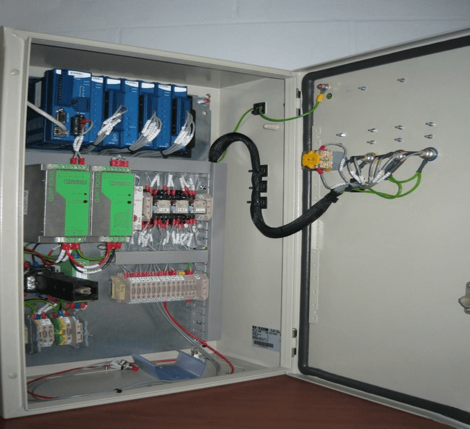
The system was developed using National Instruments Compact FieldPoint consisting of a Real Time controller (cFP-2120), a digital output module (cFP-DO-400), a high-speed analogue input module (cFP-AIO-600) and a digital output module (cFP-DI-330).

Data from the load sensors attached to the winches is analysed and compared against set ‘Load Band’ parameters. If the readings go above these parameters the system waits a defined period of time for the load to stabilise. Following this wait period, the data is once again analysed against a set of steady state parameters and if the load is within these parameters a drop has occurred and the alarm is raised. The load profile for the detected NSP drop is stored to file and the system will continue to monitor the load on all three of the winches. The alarm can be cancelled via an external ‘Cancel’ button within the site facility. Provision was also given for a suite of test profiles to be sent to the Data Logger system should verification of the system be required.

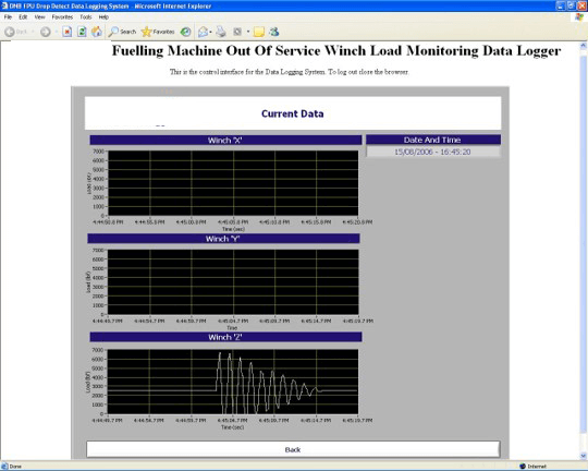
The test system for the data logger is based on MXI-4 technology. Utilising a fibre optic link (PXI-PCI8336) to a PXI chassis (PXI-1031). A data acquisition card (PXI-6221) is used to send test signals to the data logger via a conditioning box (SCC-2345) containing a voltage to current converter (SCC-CO20). The tester can be connected to any of the three winch channels (via test sockets on the enclosure) to verify its operation. This allows site personnel to input the required test profile and view the received waveform on the Web interface Screen.

Deliver

Prior to TBG Solutions developing this system our Customer had to assess how much damage an FPU had sustained due to an NSP drop, by carrying out extensive non-destructive testing of the FPU welds. Our system allows the size of the drop to be cross-referenced to the damage caused to the FPU. Site personnel will, in time, be able to look at any given drop and decide whether the FPU needs to be taken out of service for maintenance or left in service, thus preventing lost generation with a consequent loss of revenue.