Key Fact
Tests sometimes required a duration of less than 1 second yet needed to provide simulation of deceleration at up to 1000m/s⁻².

Testimonials
“TBG Solutions delivered a scalable test system that allowed all of our product to adhere to international standards”
Understand
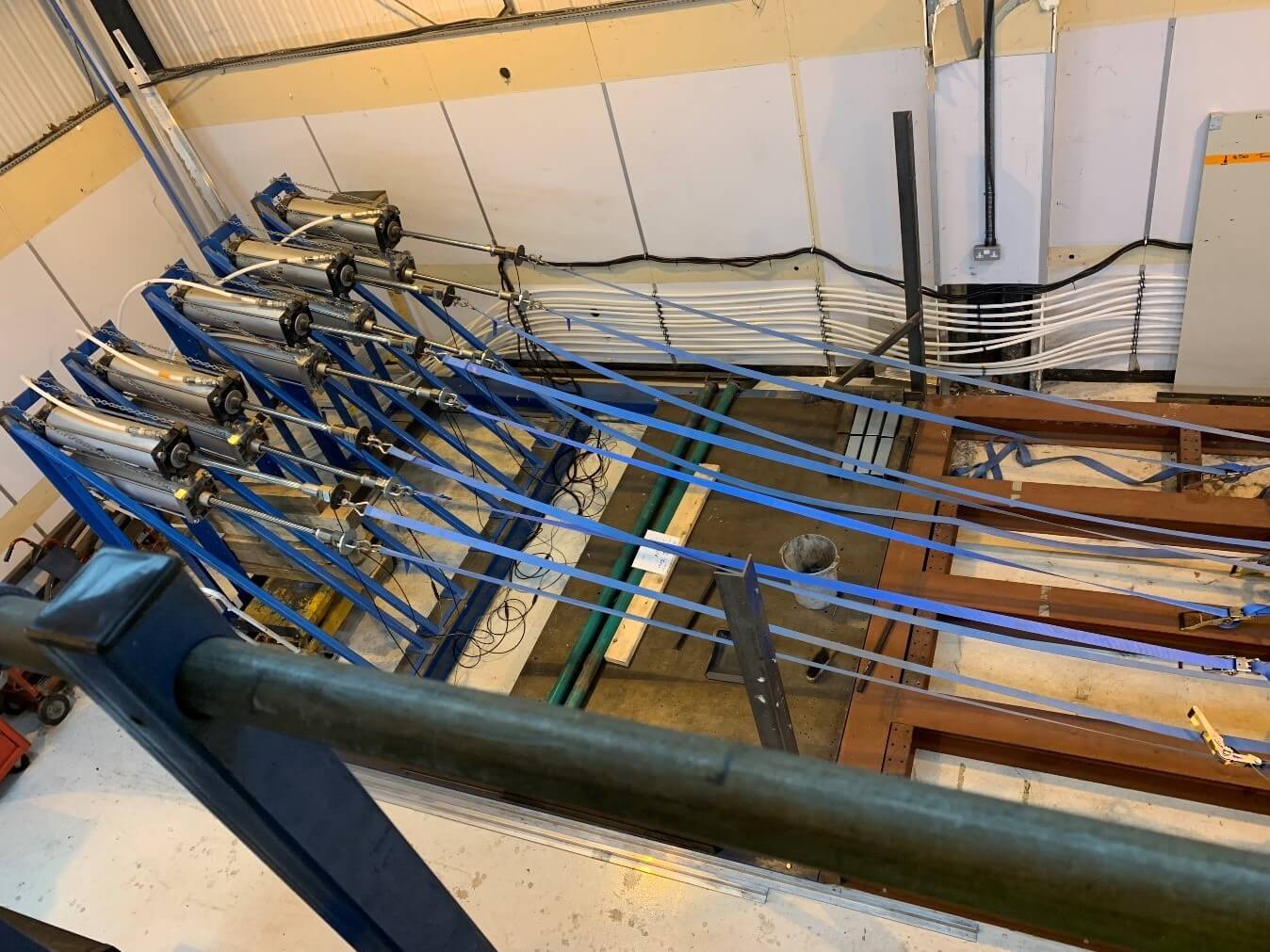
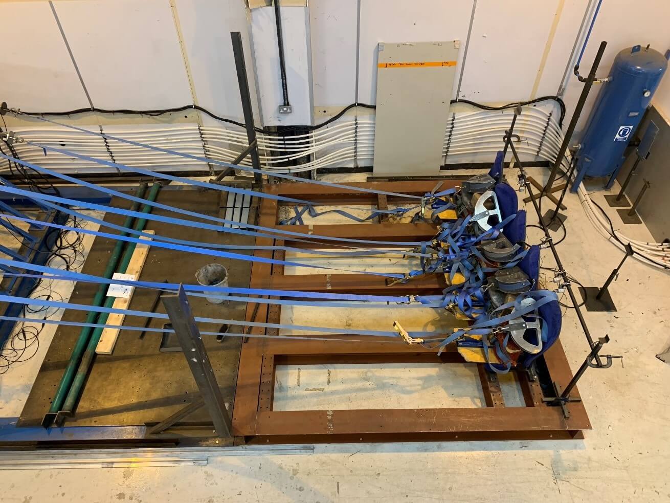
The customer approached TBG with the requirement to control a number of air driven rams to apply defined loads to varying configurations of bus seats whilst monitoring the load applied to the seatbelts for both lap and shoulder restraint.
Engineer
Project Overview
Our customer, a global bus manufacturer, approached TBG with the requirement to control a number of air driven rams to apply defined loads to varying configurations of bus seats whilst monitoring the load applied to the seatbelts for both lap and shoulder restraint.
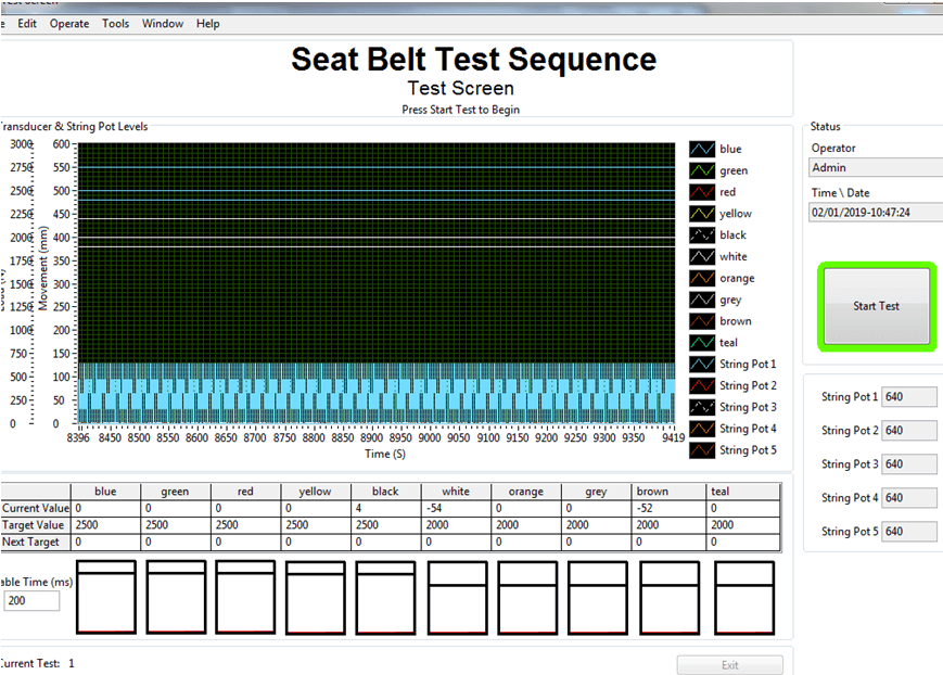
Due to the varying range of seatbelt configurations, it is important for the customer to be able to select a varying number of air driven rams, load cells and string pots for control and measurement. For this TBG solutions provide a simple to use user-friendly UI. The customer is also tied to several standards which vary internationally, so it is critical that the readings are not only accurate but repeatable with tests sometimes requiring a duration of less than 1 second yet providing simulation of deceleration at up to 1000m/s⁻².
System Design
TBG were assigned the task of interfacing several air driven rams into a hardware/software combination of TBGs choice ultimately allowing the users to have granular PID control of the testing as well as means to log and report suitable data. We chose a National Instruments LabVIEW/cRIO combination for the job. This was because is capable of running modular and reconfigurable FPGA code as well as the real time operating system meaning we could develop and run a truly real time PID algorithm.
The ability to connect an expansion chassis was also a major benefit, limited channel count meant that the string potentiometer connections had to be implemented in an ethernet expansion chassis, of which the integration into the code was seamless and easy to configure.
The ease of integration between FPGA and Real-Time meant that time and money could be saved and used elsewhere to build up the PID algorithm and reporting interface of which it was critical to be intuitive and simple.
The system can be seen to have four discrete parts:
- FPGA – Dedicated to control and acquisition on the RIO, FPGA chosen to allow for future higher data rates scan interface can’t keep up with
- Real Time – All Processing and File write functions happen here, there is also a debug interface accessible from any PC with the LabVIEW IDE
- File I/O – TDMS files are generated to log all raw data
- Reporting – The test results need to be reported, for this the report generation toolkit was used, mainly for its use of Microsoft word templates and bookmarks which meant the data from LabVIEW could easily be transposed into a professional report.
The system is ultimately controlled by a LabVIEW Real Time Executable which commands not only the FPGA acquisition via interrupts but is also responsible for all data passed up the chain to the PC. The system itself is within a simple enclosure with dedicated PSU for the CRIO and load cell excitation, of which the load cells can be excited in any combination required based upon the testing requirements. An image of the test system can be seen below.

Deliver
The final system offered a high degree of flexibility being built on top of the National Instruments LabVIEW™ platform, with the set up being designed to use a generic code system. This made the system easily expandable with plug and play simplicity and allowed for minimal changes to be made to the system’s architecture once sensors had been fitted to the nacelles.
Real-time data is channelled and gathered in a central server which forwards the data to the operator. Being controlled by independent GPS timing systems meant that data could be gathered and seen in sync in real time, ready for analysis and logging.
The facility is now ready to test the manufacturer’s latest designs in real time with an unparalleled level of accuracy and simplicity.


