Rupture Disc Case Study

Rupture disks are a critical safety component to any modern pressure based system to allow for the safe expulsion of pressure during an overpressure situation. Rupture disks are used in a wide range of industries such as automotive, pharmaceutical and aerospace.

Key Fact

Full in-house development of all hardware and software components from CAD to final products.
Testimonials

“The system has already seen production benefits by reducing pressure rupture tolerances from ±14% to <±1% putting the customer at the forefront of rupture disk production.”

Understand

Rupture disks are a critical safety component to any modern pressure based system to allow for the safe expulsion of pressure during an overpressure situation. Rupture disks are used in a wide range of industries such as automotive, pharmaceutical and aerospace. In overpressure situations, it is integral that the disks rupture within low tolerances of their defined overpressure limit to avoid potential disaster and damage to the system.

The production of rupture disks has historically been a manual, analogue based process using a large 5 tonne steel press, multiple gauges and indicators all controlled by a single operator. Complexity of the production process results in high tolerances of the burst pressure of the disk itself which push the limits of design specifications.

The overall issue of high pressure limit tolerances and the expensive, time consuming nature of the production process led to the customer selecting TBG Solutions to re-engineer and automate the production process due to our vast experience in providing bespoke automated production test and measurement solutions.

Engineer

The system is responsible for control and automation of 5 key areas of the production process:

Hydraulic Press Control – Providing necessary clamp forces to hold the sheet material in place.

Tooling – Decision making on specific tools to use during the forming process as well as being able to control the disc geometry during forming.

Hardware control – Control all electromechanical hardware in the system such as valves and pressure transducers.

Disk forming – Control and configuration of all settings and hardware to produce a rupture disk.

Logging of data – Press profiles and all user data including login information, press diagnostics and pressure data are all stored in CSV & database files.

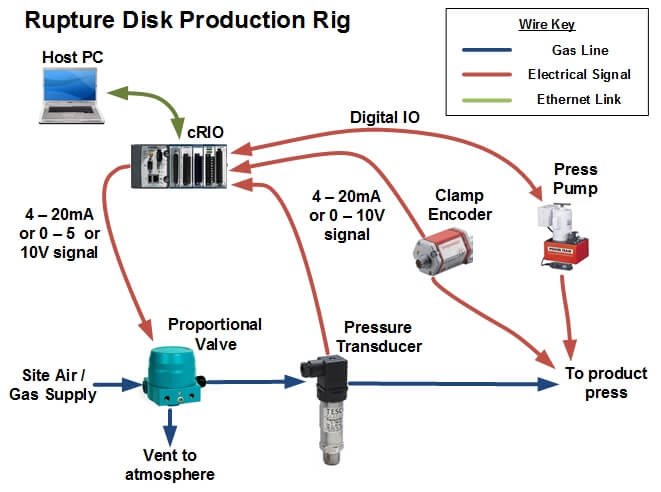
Overall, the system is controlled by a LabVIEW application running on a host PC which communicates via Ethernet with a cRIO-9014 real-time controller and 9104 FPGA based chassis. Communication between the new system & existing hardware such as pressure transducers and pumps is done so via a combination of FPGA based digital signals on the cRIO as well as custom Windows DLL functions to communicate with external software including configuration software for a PID pressure controller.

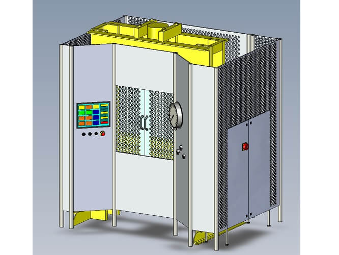
As well as having the design challenge of software development, careful consideration of the overall enclosure of the system was required by TBG Solutions Glasgow due to the nature of the application operating in a high pressure, wet environment and its inherent risks to the operator from a 5 tonne steel press.

A fully operational enclosure for the press and all associated hardware was produced in-house, this allowed for a high level of customisability of the final build as well as ease of integration of NI and 3rd party hardware in the same IP rated enclosure.

Deliver

Overall, the combination of reconfigurable Real-Time and FPGA based hardware coupled with the ease of development and UI customisability in the LabVIEW IDE provided TBG Solutions with the means to understand, engineer and deliver a turnkey solution to the customer, fitting the initial brief and specification and exceeding customer expectations.

Using LabVIEW & cRIO, we were able to integrate with existing hardware to produce an easy to use modern production process that has already seen production benefits by reducing pressure rupture tolerances from ±14% to <±1% putting the customer at the forefront of rupture disk production.
University Of Southampton Case Study

Renowned for its award-winning research projects in science, technology and engineering, The University Of Southampton is a world-famous research facility.

Key Fact

Adaptive algorithms enabled the system to be robust and capable of reducing multiple and varying noise frequencies.

Testimonials

“Implemented on embedded system technology providing a state of the art, highly reliable, compact and adaptable system.”

Understand

The TranQuil project is a collaboration with Princess Yachts, The University of Southampton and TBG Solutions. Princess Yachts, designers and manufacturers of motor yachts, are regarded as the finest exponent of contemporary yacht design. The project was aimed at the luxury yacht market. Yachts often use a secondary generator to provide power whilst the yacht is stationary, however, this generates considerable noise and vibration, which can upset passengers during silent hours.

The challenge was to develop a scalable and frequency adaptable solution that nullified generator noise and reduced vibration thus providing maximum comfort to passengers.

Engineer

The proposed system was a set of actuators that sit beneath the generator moving in anti-phase and amplitude to the generator, thus eradicating noise and vibration. This presented additional challenges as the system needed to be reactive to multiple points of contact and react in real time (microseconds) to vibrations in order to be effective.

Adaptive algorithms enabled the system to be robust and capable of reducing multiple and varying noise frequencies.

Deliver

TBG Solutions achieved active noise cancellation by implementing a Least Mean Square (LMS) algorithm.

The system successfully reduces cabin nose by 10dB providing passengers with a highly reliable, compact and state of the art system to ensure maximum comfort. This system can be built-in to new boats, retrofitted to existing boats and applied in other industries where noise and vibration cancellation is required, such as in coaches and buildings.

Tridonic Case Study

Tridonic is a global business working to control, regulate and operate lighting systems in accordance with its customers’ needs. With over 50 years’ experience and a 2,000-strong team of experts, Tridonic is a global leader in the lighting industry.

Key Fact

The unit is fully equipped to test a full range of products without the need for adjustments

Testimonials

“TBG Solutions’ delivered system integrates seamlessly with a whole variety of hardware.”

Understand

Tridonic is a leading manufacturer of lighting components, developing innovative solutions that are used worldwide in the lighting industry. The company is highly focused on customer satisfaction and quality.

The brief was to engineer a bespoke and specialised test system that could efficiently test and quality check a range of different lighting products before being sent to customers to ensure they were fully functional and of the highest quality.

Engineer

The system needed to be highly adaptable so that it could be used to test a full range of LED products and test each unit using multiple AC/DC power supplies. The system needed to be capable of testing light levels, voltage/current tolerances and perform flash testing, all whilst keeping test time to a minimum and efficiency high.

The engineering challenge was to develop a generic system that was able to test a full range of products. This was overcome by the use of multiple product carriers along with an object-oriented architecture allowing for future expandability and maintenance of the bespoke system.

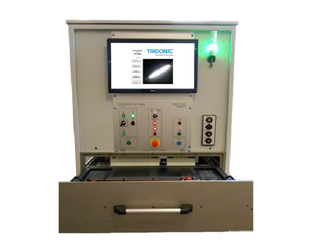
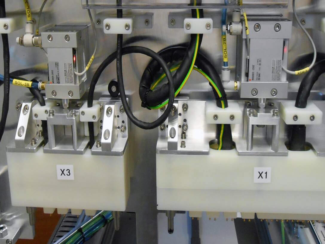
The solution was designed so that the product to be tested is placed in a drawer where specially designed, air driven probe blocks (two at the back and one underneath) are positioned to make the required physical connections, successfully testing and quality checking each product before shipping.

Deliver

The testing unit was successfully delivered and stands at over six feet tall. The unit is fully equipped to test a full range of products without the need for adjustments by simply placing the product into the testing platform drawer. The system tests each product at a high degree of accuracy at peak efficiency; it also has the benefit of being fully scalable for future projects.

Automated Test System to Test Seat Belt Quality Case Study

Seat belts reduce the risk of a fatal injury by up to 50 per cent for front seat occupants and up to 75 per cent for rear seat occupants. They have to meet a variety of standards to be allowed in vehicles.

Key Fact

Tests sometimes required a duration of less than 1 second yet needed to provide simulation of deceleration at up to 1000m/s⁻².

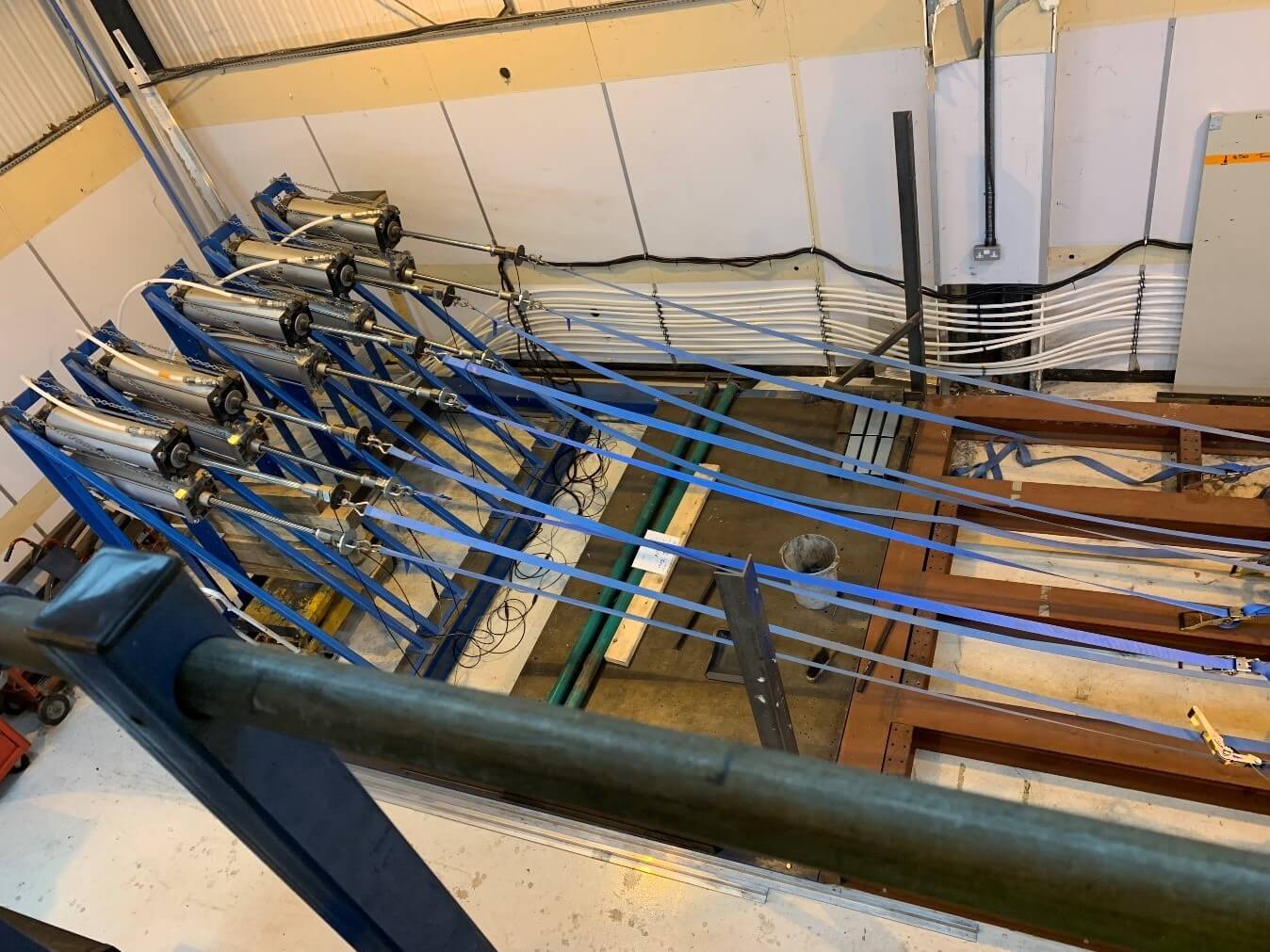
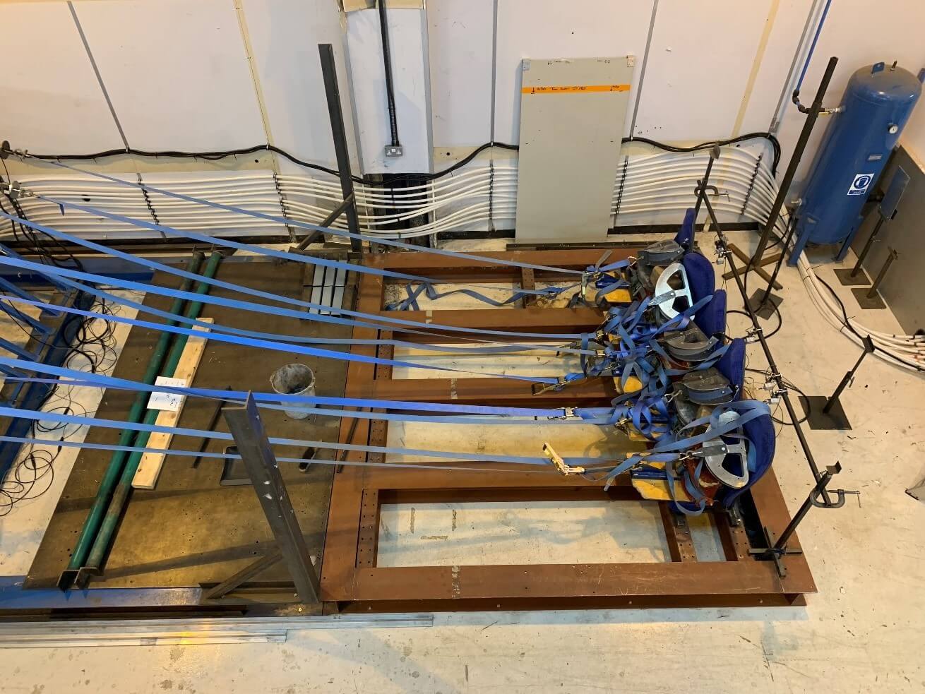
General System (Top – Seats) (Bottom – Rams)

Testimonials

“TBG Solutions delivered a scalable test system that allowed all of our product to adhere to international standards”

Understand

The customer approached TBG with the requirement to control a number of air driven rams to apply defined loads to varying configurations of bus seats whilst monitoring the load applied to the seatbelts for both lap and shoulder restraint.

Engineer

Project Overview

Our customer, a global bus manufacturer, approached TBG with the requirement to control a number of air driven rams to apply defined loads to varying configurations of bus seats whilst monitoring the load applied to the seatbelts for both lap and shoulder restraint.

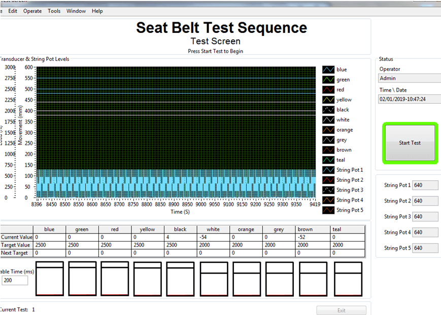
Due to the varying range of seatbelt configurations, it is important for the customer to be able to select a varying number of air driven rams, load cells and string pots for control and measurement. For this TBG solutions provide a simple to use user-friendly UI. The customer is also tied to several standards which vary internationally, so it is critical that the readings are not only accurate but repeatable with tests sometimes requiring a duration of less than 1 second yet providing simulation of deceleration at up to 1000m/s⁻².

System Design

TBG were assigned the task of interfacing several air driven rams into a hardware/software combination of TBGs choice ultimately allowing the users to have granular PID control of the testing as well as means to log and report suitable data. We chose a National Instruments LabVIEW/cRIO combination for the job. This was because is capable of running modular and reconfigurable FPGA code as well as the real time operating system meaning we could develop and run a truly real time PID algorithm.

The ability to connect an expansion chassis was also a major benefit, limited channel count meant that the string potentiometer connections had to be implemented in an ethernet expansion chassis, of which the integration into the code was seamless and easy to configure.

The ease of integration between FPGA and Real-Time meant that time and money could be saved and used elsewhere to build up the PID algorithm and reporting interface of which it was critical to be intuitive and simple.

The system can be seen to have four discrete parts:

  • FPGA – Dedicated to control and acquisition on the RIO, FPGA chosen to allow for future higher data rates scan interface can’t keep up with
  • Real Time – All Processing and File write functions happen here, there is also a debug interface accessible from any PC with the LabVIEW IDE
  • File I/O – TDMS files are generated to log all raw data
  • Reporting – The test results need to be reported, for this the report generation toolkit was used, mainly for its use of Microsoft word templates and bookmarks which meant the data from LabVIEW could easily be transposed into a professional report.

The system is ultimately controlled by a LabVIEW Real Time Executable which commands not only the FPGA acquisition via interrupts but is also responsible for all data passed up the chain to the PC. The system itself is within a simple enclosure with dedicated PSU for the CRIO and load cell excitation, of which the load cells can be excited in any combination required based upon the testing requirements. An image of the test system can be seen below.

Deliver

The final system offered a high degree of flexibility being built on top of the National Instruments LabVIEW™ platform, with the set up being designed to use a generic code system. This made the system easily expandable with plug and play simplicity and allowed for minimal changes to be made to the system’s architecture once sensors had been fitted to the nacelles.

Real-time data is channelled and gathered in a central server which forwards the data to the operator. Being controlled by independent GPS timing systems meant that data could be gathered and seen in sync in real time, ready for analysis and logging.

The facility is now ready to test the manufacturer’s latest designs in real time with an unparalleled level of accuracy and simplicity.

Test Interface (Using Simulated Data)

Creating an automated HASS test solution for three avionics PCBs.

HASS testing (Highly Accelerated Stress Screen) is an accelerated reliability screen that can reveal latent flaws accessing product reliability.

Key Fact

The system led to 12x increase in test throughput, benefiting the manufacturer and ultimately the consumer with a significant cost reduction.

Testimonials

“The test system ensured that all of our PCBS are properly tested prior to use and has significantly decreased our test time.”

Understand

Manufacturing flaws and reliability problems can cause mission changing or even catastrophic and fatal consequences as well as significant financial penalties in the avionics defence industry. To help mitigate this, original equipment manufacturers are required to perform HASS testing to ensure ongoing product quality and reliability by exposing latent defects in components and assemblies. HASS testing is a form of stress test for a product designed to improve reliability by characterising failures and using this information to improve on the design or manufacturing process. Temperature and vibration cycling are commonly performed during the HASS testing process.

The requirement to test three avionics RIO (Remote Input/Output) PCBs in parallel led to the employment of TBG Solutions. TBG Solutions is a National Instruments Gold Alliance Partner that specialises in providing bespoke automated production test and measurement solutions, system maintenance, customer training and support for a diverse customer base.

Engineer

The Test System

The test system performs 50,000 electrical tests including voltage, resistance, current, capacitance, frequency, phase and trip on three parallel units residing in a HASS chamber. The test system allows HASS profiles to be generated and executed, giving the operator the ability to exclude or include specific tests, adjust temperature/vibration levels and ramp rates. The fully automated parallel testing involves aircraft simulation, 2-part firmware download, highly accurate capacitance measurements and load trip testing.

The test system utilised a National Instruments PXI-8106 controller and PXI-1045 18 slot chassis with three PXI-4065 DMMs, a PXI-5105 Scope, Multifunction DAQ cards and various switch cards to allow extremely accurate, flexible and easy measurements. LabVIEW was used to create an interface driver for each instrument within the system and TestStand was then used to seamlessly sequence these drivers and other components together to create flexible test sections that could then be sequenced on the fly. TestStand has built-in parallelisation options and these were taken advantage of to test the three units as a batch, starting and ending the testing together.

The complete system was designed and built by TBG Solutions and TBG Manufacturing using CAD/CAM and National Instruments LabVIEW/TestStand

Figure 1 shows a CAD image of the test system with the National Instruments PXI hidden behind a panel accessible from the rear of the 2-bay 19” rack.

Benefits of the Test System

The test system not only tests three units in parallel but brings the individual test time for a single unit down from 3 hours using an existing system to 45 minutes. This provides a 12x increase in test throughput, benefiting the manufacturer and ultimately the consumer with a significant cost reduction.
Software tools provided with the system allow the user to change test sequencing/looping and HASS parameters such as vibration level, temperature level and respective ramp rates. This allows the customer to create a very specific test profile to try and replicate a real-world fault on a particular component. This moves the system away from a rigid test system and allows the customer to perform diagnostics, debug testing and R&D.

•    Automated parallel test of multiple units

•    150 000 Individual tests

•    Plane simulation

•    Environmental chamber control with condition profiling

LabVIEW and TestStand provided such a comprehensive suite of easy to use functionality that the developers and designers were able to really focus on the best way to perform the tests on the unit rather than building the test executive. The team leveraged the functionality of LabVIEW and TestStand and other National Instruments products to provide a flexible, maintainable system, fit for purpose at the present and long into the future. Utilising these technologies allowed development of highly cohesive and loosely coupled tests increasing flexibility of test and reusability of software modules.

The final system successfully performs over 50,000 tests per unit under test in parallel whilst controlling the HASS chamber.

Deliver

LabVIEW and TestStand provided such a comprehensive suite of easy to use functionality that the developers and designers were able to really focus on the best way to perform the tests on the unit rather than building the test executive. The team leveraged the functionality of LabVIEW and TestStand and other National Instruments products to provide a flexible, maintainable system, fit for purpose at the present and long into the future. Utilising these technologies allowed development of highly cohesive and loosely coupled tests increasing flexibility of test and reusability of software modules.

The final system successfully performs over 50,000 tests per unit under test in parallel whilst controlling the HASS chamber.

Figure 1: Computer Aided Design (CAD) Image of Test Equipment Rack
Figure 2: User Interface for Test Equipment

Automated Test System for Functional and In-Circuit Testing Case Study

The automated test system we developed for functional test and in-circuit testing allows testing for multiple product ranges and is easily scalable for future expansion requirements.

Key Fact

New products can be supported by designing additional interchangeable test adaptors (ITA) which can be easily fitted to the system

PCB Test

Testimonials

“TBG Solutions delivered a functional test system that is effective and easily expandable.”

Understand

TBG Solutions have produced a PXI based generic automated test system performing both functional test and in-circuit testing on multiple products ranges.

The system leverages the MacPanel scout interface to provide a reconfigurable base platform from which the system can easily and quickly adapted in order to test a wide range of products. The system comprises enough hardware to support most test functions and can be expanded to support additional hardware where required.

The software architecture is modular and comprises elements common to all product test applications such as user management, calibration and diagnostics. The software is expanded to facilitate product specific testing by implementing custom TestStand sequences. New products can be supported by designing additional interchangeable test adaptors (ITA) which can be easily fitted to the system. New software sequences can be written specifically for each ITA expanding the functionality of the system.

Engineer

Design Challenges

The challenge was to design a versatile PXI based system incorporating a mixed suite of measurement hardware that can be re-configured and re-used for testing multiple product types using a commaon base platform. A product specific Interchangeable test adaptor is attached to the base system to provide the signal routing and configuration applicable to the tests required for that specific product.

Due to the nature of the project there would be a lot of electrical noise, limiting the distance that data could be transmitted. This posed a problem since operations needed to be logged at high accuracy and in real time.

System Design

National Instruments PXI measurement hardware provides the basis for the Generic Manufacturing Defect Inspection Automated Test Equipment (GMDI-ATE) which is further augmented using Excelsys Xgen™ range power supplies. The system is mounted in a standard 19” rack enclosure and incorporates a MacPanel Scout interface for configuring the system for different applications.

NI-PXI hardware modules provide a large number of analogue and digital channels working in tandem with high density switch and relay matrixes. In addition, we include a high precision DMM, arbitrary function generator, fully reconfigurable FPGA, RS232/485 serial communications, CAN and JTAG boundary scan.

Deliver

The systems delivered to date have successfully managed to reduce the cost of ownership and lead times on providing new test capabilities whilst improving test performance, accuracy, traceability and throughput. TBG can augment your test capabilities by designing and producing an ITA in under eight weeks.

In-Circuit Test System

Automated Test System for Critical Testing of Aerospace Grade Units Case Study

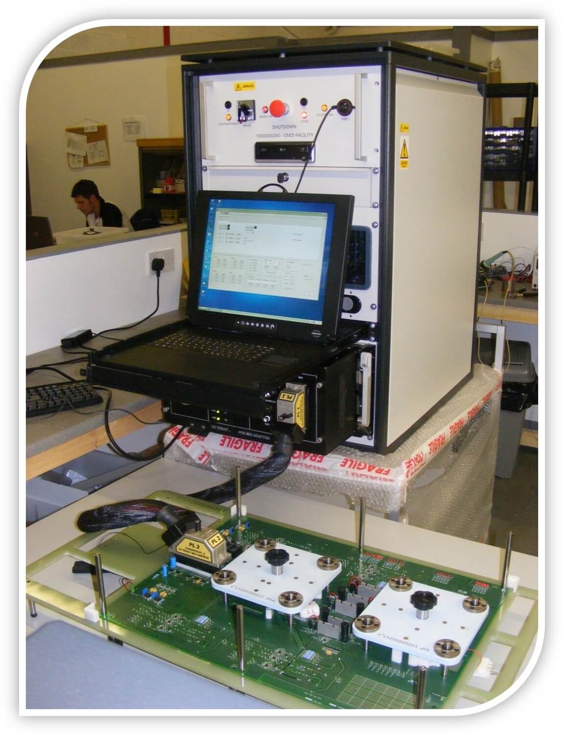
We converted an existing manually controlled friction brake test system into a software-controlled automated test system, critical for testing aerospace-grade units.

Key Fact

The software needed to allow the operator to control all aspects of a Parker Compax3 drive and MH series 10000rpm motor.

Testimonials

“The system ensures a level of quality control that is required by a modern Aerospace company.”

Understand

The customer is one of the world’s leading Aerospace companies, specialising in actuator and motor systems for a range of aircraft.

They approached TBG with the requirement to convert an existing manually controlled friction brake test system into a software controlled automated test system, critical for testing aerospace grade units. The software needed to allow the operator to control all aspects of a Parker Compax3 drive and MH series 10000rpm motor.

Initially, the customer was told by other integrators that this would not be possible. However, the experience of TBG Solutions and our capabilities gave us the confidence that this could be done and not only could we produce the software in house, but also make use of our in house mechanical and electrical expertise to make changes to the inner workings of the test rig to allow for full control in software.

Engineer

The Solution

The solution is a bespoke LabVIEW application that allows for full control of the motor drive as well as a profiling application to allow for automation and sequencing of ramp rates and dwell times, to fulfil the critical test specification of the UUT.

We were able to make use of the LabVIEW IDE and its prebuilt functions for serial RS232 communications to build a OOP based HAL for the Parker Compax3 Motor Drive. This provides flexibility and scalability for communication between multiple systems and different motors.

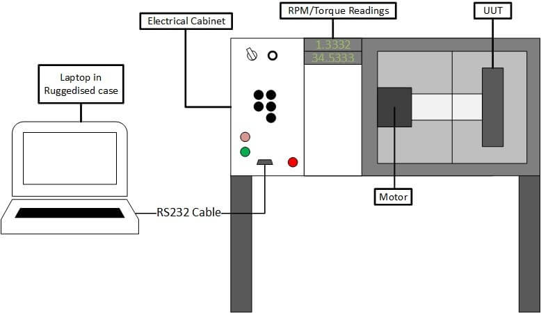
Feedback from this Parker Compax3 motor is also displayed on COTS indicators showing the speed and torque on the shaft and UUT. The system itself connects via RS232 to a laptop within a rugged Pelican case designed and manufactured in house by TBG solutions to the highest standards. A basic system overview can be seen in Figure 1.

The Application

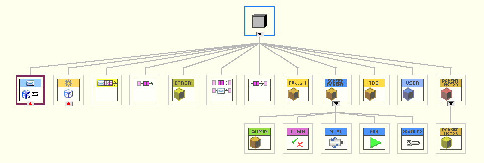
The application makes use of the OOP programming architecture. This coupled with TBGs own OOP based QMH design pattern allows for a scalable application architecture where events and error handling are organised and reliable.

Figure 1 - General System Overview
Figure 1 – Class Hierarchy

Communications

The key challenge in this project was working to ensure that we could achieve stable and reliable communications with the 3rd party device. Due to there being no driver being provided by the manufacturer, TBG had to revert to using our experience in driver production as well as the comprehensive serial communication user manual for the motor drive. The driver created is the first of its kind for the Compax3 series of motor drives. LabVIEW’s acceptance of a HAL environment means that the software is scalable to multiple test sets and can be transferred over to other motors and drives in the Parker portfolio. The HAL based driver set for the motor drive handles all initialisation, read/write, error handling and shutdown controls for the motor drive. An example of the read-write code can be seen in figure 2.

Figure 2 – Motor Read/Write Driver

User Interface

The User Interface of the application can be split into 4 discrete parts which are:

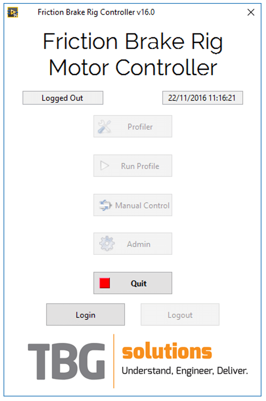
·        Main Interface – This the main launcher where a user can select different screens dependent on their requirements such as the profile editor, manual control or even user management. All buttons are enabled/disabled based upon the user’s credentials (i.e. admin, engineer or operator).

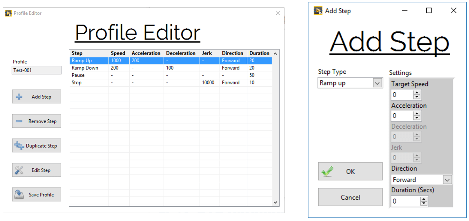
·        Profiler – This is where the user can create or edit a test profile for UUT testing. They have full control over adding and removing steps. When adding steps, they can ramp up, ramp down, dwell or stop. The add step popup will dynamically change the available step options based upon the step chosen. The options include direction, acceleration and speed.

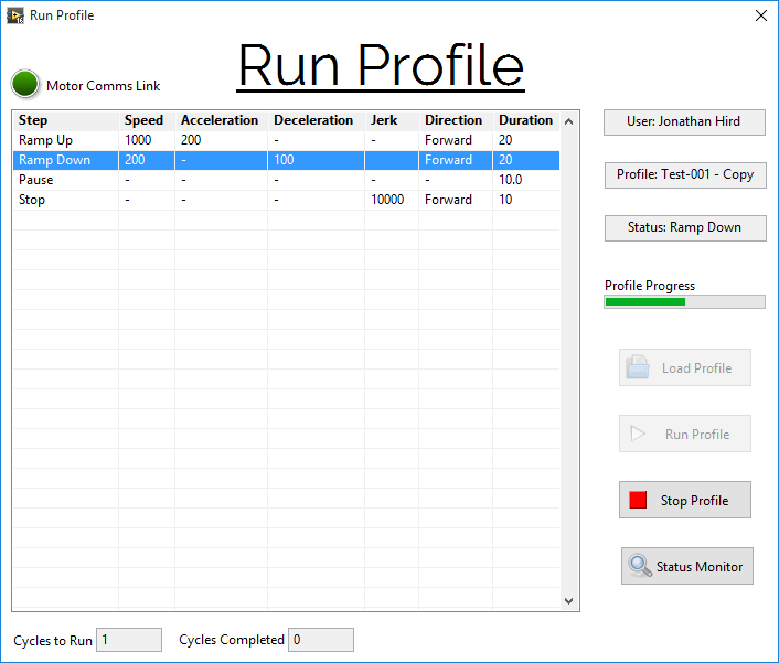
·        Run Profile/Test – This is where a profile can be loaded and run, and in turn, commands sent to the motor drive to test a UUT (as seen in figure 5).

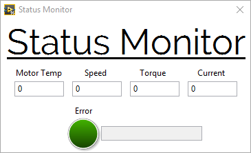
The user can see the loaded steps of the profile and can set the system to run multiple cycles of the same test whilst viewing critical data such as motor temperature and voltage via an asynchronously loaded status monitor, as seen in figure 6.

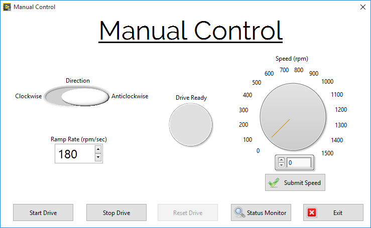
·        Manual Control – As well as automating the test procedure, the user may require manual control of the motor to debug a potential issue with the UUT or run the UUT to a high speed with maximum control. This is done via a dedicated manual control screen (as seen in figure 7) which utilises the same HAL based commands to the motor drive. The screen is constantly monitoring interlock and e-stop conditions to ensure that operation can’t take place whilst a guard door is open or when the system is in an E-Stop situation. The user is granted full control of direction, ramp rate and speed with this screen whilst again making use of viewing critical data in the status monitor.
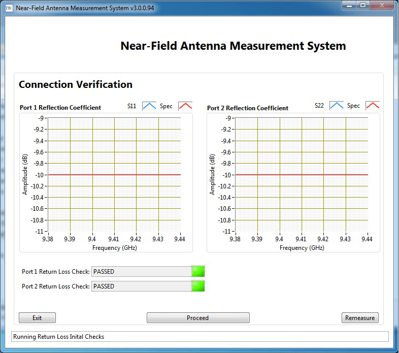
Figure 3 – Main Interface
Figure 4 – Profile Editor and Step Editor
Figure 5 – Profile Editor and Step Editor
Figure 6 – Status Monitor
Figure 7 – Manual Control Screen

Deliver

Since delivery, the system has tested hundreds of units and runs daily with the customer reporting good feedback on the usability and reliability of the system, keeping them on track in terms of units tested and keeping them at the forefront of the aerospace industry. The use of the LabVIEW OOP capabilities allowed us to create an application that not only exceeds customer expectations but also allows for a fully scalable design architecture which serves as a base foundation for further systems and other projects.

Building a Scalable Antenna Test System Case Study

A case study on an Antenna Test System we built for one of our customers to test the antenna response on a user-defined range of frequencies.

Key Fact

The system can test the antenna response on a user-defined range of frequencies (expanding on the limited S and X Bands), both stationary, and along the length of the antenna.

Testimonials

“The Antenna Test system exceeded the original Test Software surpassing the test specification and has now replaced the old system completely in a production environment as confidence in the software is so high.”

Understand

Introduction

Modern technology heavily relies on a wide range of transmissions, from simple AM Radio to Satellite Tracking Systems. All EM Communications require an antenna for both Transmission and Reception, making the production and supply of antennas a huge industry. Some suppliers push the boundaries on antenna size providing devices we rely on every day to be smaller and slimmer, such as Mobile Phones or the Bluetooth Antenna in your Smart Watch. Others, as in the case of our customer, push the boundaries on complexity, providing smarter RADAR and Detection systems that keep Ships and Aircraft safe.

TBG Solutions was contracted by the customer to update an existing Antenna Test System, written in a now unsupported software language. Unfortunately, the Source Code was no longer available and Test System had to be redesigned from scratch. TBG Solutions was involved from the beginning of the update project, to design and implement a modern test system. The test system needed to be expandable, hardware independent and compatible with multiple Network Analysers.

Antennas

Antennas are using in a wide range of industries and vary dramatically by both size and complexity. The range of frequencies each antenna is designed and tuned for can also vary significantly. The Antenna Test System was designed to test large RADAR antennas, designed and supplied to the Marine Industry. The frequency range of the Antenna Test System covers both the S and X Bands. S-Band covers 2-4GHz and is used by Surface Ship RADAR, as well as some communications satellites. The X-Band however, covers the higher range of 8-12GHz and is used in military Satellite Communications, along with more advanced RADAR.

Engineer

Our Solution was a system that could test the antenna response on a user-defined range of frequencies (expanding on the limited S and X Bands), both stationary, and along the length of the antenna. These measurements included both Phase and Magnitude on both Transmission and Reception, and measurements could also be expanded to include frequency sweeps at differing power levels. This gave the user full control over the measurement type.

Test System Design

The Modernised Test System was designed using NI LabVIEW Object Orientated Programming, along with an NI GPIB Card to Communicate to a Network Analyser which is used to conduct the tests. Due to the expandable nature of LabVIEW, especially when developed using Object Orientated Design Principles, we were able to design a system that could be quickly and easily updated to work on any programmable Network Analyser.

The Analyser was used to capture the responses to both transmission and reception for a specific Antenna. The test system captured “S” measurements (S11, S21, S22) and calculated both Phase and Magnitude for the captured responses.

The Antenna Measurement System Hardware

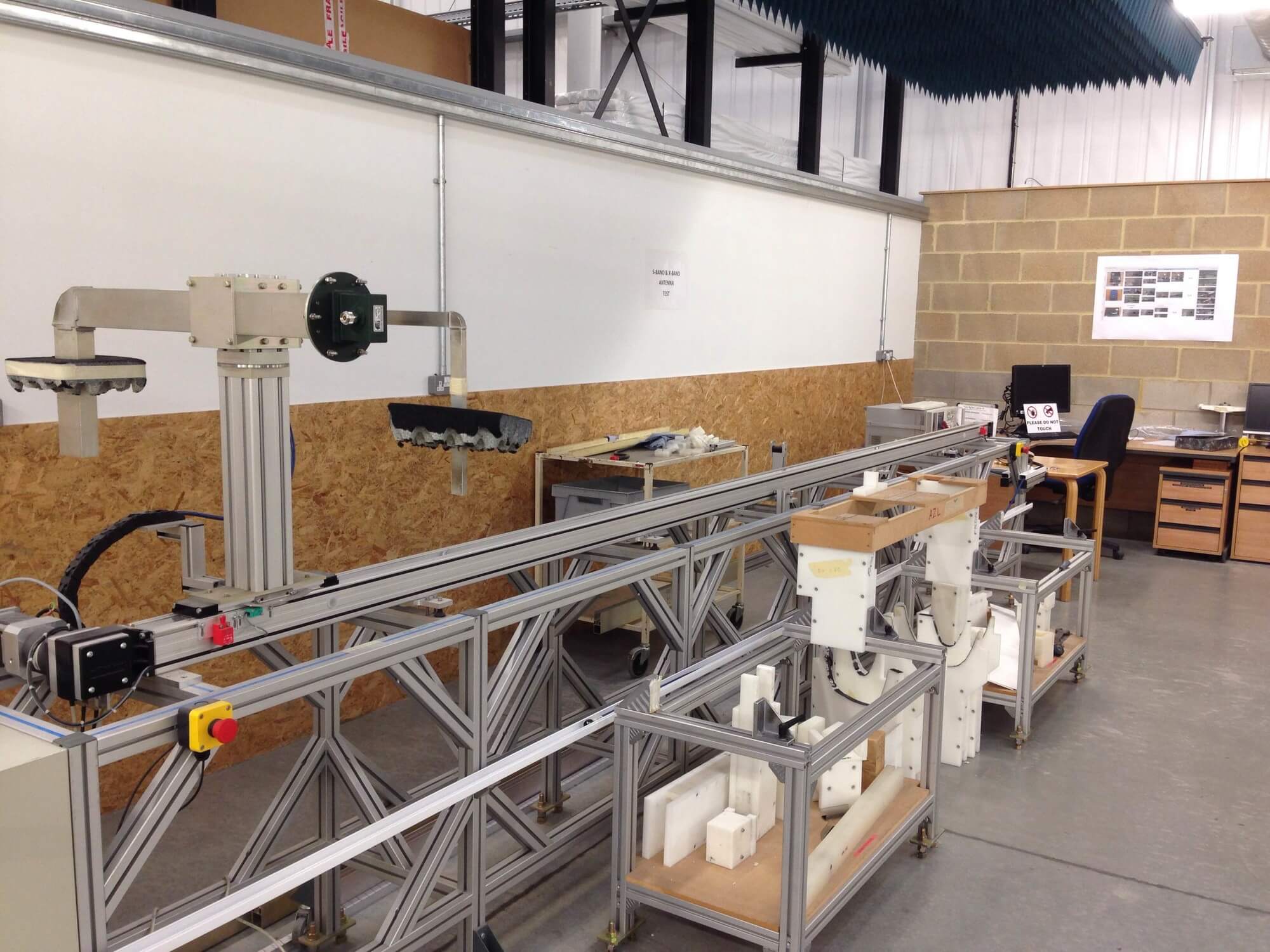
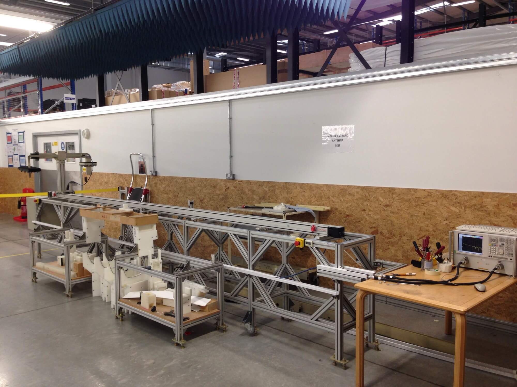
The test system also comprised of a Step Motor that allowed the Test Software to move the test probe along the length of the antenna while simultaneously taking measurements. This allowed our customer to build a complete antenna profile which could be used in both design and verification activities. This data was then post analysed to generate Near Field and Far Field data allowing our customer to verify that their antenna or component was functioning correctly and responded as expected in real-world tests.

The Antenna Measurement Probe

Test System Software

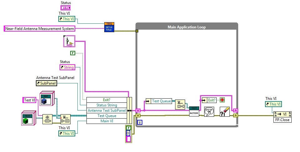
The control software for the Antenna Test System was written entirely in National Instruments LabVIEW. Using LabVIEW allowed us to construct an expandable and complex test system in a much shorter time than other text-based languages. The graphical nature of LabVIEW also allowed us to easily demonstrate the functionality and instruct our customer on making minor modifications to the functions of the Test System.

The Test System software was completed using Object Orientated Design principles which allowed us to develop Simulation Modules of all of the hardware in the system. This made debug very simple and independent of hardware. Once this was complete we were able to more easily develop modules for physical hardware (two different Network Analysers were required to be compatible, with more in the future).

Object Orientated Programming is a framework that allows code to be written using a generic module or “Class” for each of the functions of a piece of hardware (or function). An example would be taking a reading from a Network Analyser. This generic module is then used to create a specific module for a specific piece of hardware creating a “Child Class”. There can be multiple Child Classes with one for each specific piece of hardware. These Child Classes are automatically substituted when the software is run depending on the hardware element is selected. This makes adding new hardware simple as no changes to the software’s code are needed to facilitate additions. (except creating a new Child Class).

While coding modules, LabVIEW automatically checks that all the requirements for a Class are met, and reports any issues clearly. This allows an Object Orientated System to be coded by a developer with limited knowledge of the principles behind its operation.
The Antenna Measurement System Software
LabVIEW Object Orientated Programming Streamlines Code

Deliver

Results

The Antenna Test system exceeded the original Test Software surpassing the test specification. This Test System has now replaced the old system completely in a production environment as confidence in the software is so high. The system not only improves reliability, it also expands in the following areas:

·        Data is provided at a much lower level, as well as a top-level result, allowing our customer to investigate design issues at a much lower level.

·        The New System is already compatible with two differing hardware sets (which surpasses the old system), With more to be added as required.

·        Our Customer is no longer tied to a specific (and expensive) Network Analyser, they are now free to explore cheaper options.